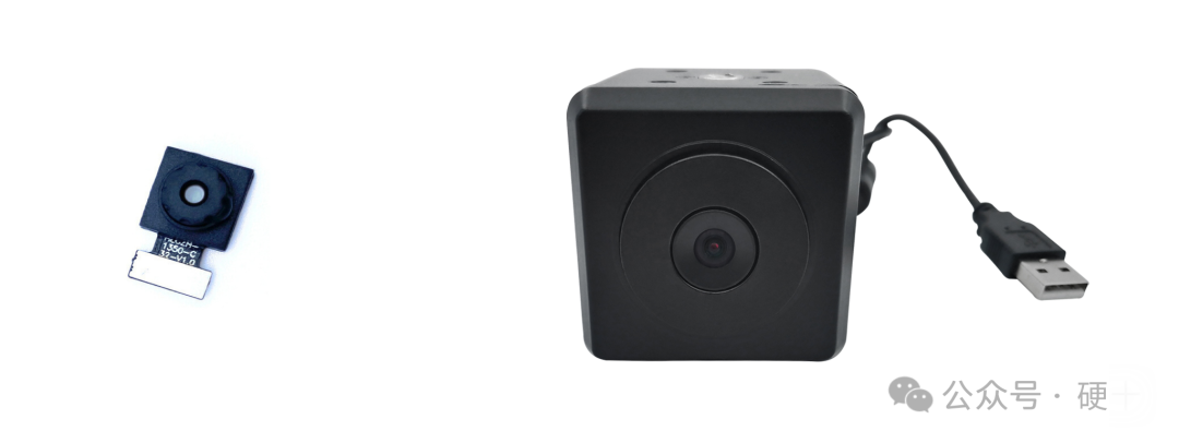
We must first understand the basic differences and application scenarios of these two protocols. MIPI is typically used for internal communication between components in mobile devices, such as cameras and displays, while USB is more for connecting external devices like USB drives and peripherals.
1. MIPI interface cameras support high resolutions and high frame rates, easily accommodating high pixel requirements such as 5 million and 8 million pixels.
2. Native MIPI cameras can directly perform DMA transfers, support processing through ISP, and can also obtain raw RAW data.
3. MIPI cameras are relatively economical, while USB cameras of equivalent specifications tend to be more expensive.
4. MIPI cameras have a faster startup speed, suitable for immediate use after powering on, while USB cameras have a slower startup speed.
5. MIPI cameras feature low power consumption, effectively reducing energy usage, whereas USB cameras generally have higher power consumption.
6. MIPI requires drivers, while USB is generally driver-free.
7. MIPI is relatively more reliable than USB; MIPI is less prone to recognition issues, while USB is prone to disconnections.
Why is the MIPI protocol more efficient, cheaper, and has lower latency than the USB protocol?
First, the design goal of MIPI is primarily to enable high-speed, low-power data transmission within devices, so the data packet structure is more streamlined. In contrast, USB needs to support various device types and more complex control functions, such as hot-swapping and power management, which increase the protocol’s overhead.
Next, at the physical layer, MIPI uses differential signaling and more efficient encoding methods, such as LVDS (Low-Voltage Differential Signaling). This technology reduces electromagnetic interference, improves transmission efficiency, and minimizes the need for additional error correction and data retransmission. Although USB also uses differential signaling, it may require more error detection and correction mechanisms, such as CRC checks, due to the need to accommodate longer cables and more external interference, which increases overhead.
Additionally, the MIPI protocol is typically point-to-point or short-distance board-level connections, allowing it to omit some fields used for routing and addressing. USB supports multiple devices connected through a Hub, requiring each data packet to include device addresses, endpoints, and other information, resulting in larger header information and increased overall overhead.
Moreover, MIPI’s protocol stack may be more simplified, focusing on data transmission itself, while USB’s protocol stack includes more layers, such as transaction and transport layers, each adding control information and processing steps, leading to more overhead.
However, I need to confirm the specific MIPI protocols, such as MIPI D-PHY or MIPI CSI-2, to see if their data packet structures have less header information. For example, CSI-2 may use a more compact packet format, while USB’s each transmission transaction requires token packets, data packets, and handshake packets, each with its own header, resulting in greater cumulative overhead.
Furthermore, MIPI may operate at higher clock rates, but due to the efficient design of the physical layer, the actual effective data rate is higher. In contrast, while USB may not have low rates, the additional information in the protocol leads to a lower payload ratio. For instance, USB 3.0’s SuperSpeed protocol includes various control packets at the link and protocol layers, while MIPI may be more streamlined in these aspects.
In summary, the reasons MIPI protocol has lower overhead may include: more streamlined data packet structures, more efficient physical layer designs, point-to-point connections reducing addressing needs, and a simplified protocol stack. In contrast, USB, due to its versatility and complex functional requirements, needs more control fields and error handling mechanisms, resulting in larger overhead for each data packet.
The MIPI (Mobile Industry Processor Interface) protocol has lower overhead compared to the USB (Universal Serial Bus) protocol, primarily reflected in the following aspects:
The MIPI (Mobile Industry Processor Interface) protocol has lower overhead compared to the USB protocol, primarily reflected in the following aspects:
1. Optimized Physical Layer Design
- Low-Voltage Differential Signaling (LVDS): MIPI D-PHY uses low-swing differential signaling (typical voltage swing around 200mV), resulting in lower power consumption and supporting high-speed transmission (e.g., MIPI CSI-2 can reach 10 Gbps). In contrast, USB (e.g., USB 3.0) requires higher voltage swings (e.g., USB 3.0’s transmitter voltage is 1.0V), leading to higher power consumption.
- Point-to-Point Communication:MIPI is mainly used for short-distance connections within devices (e.g., cameras, displays), where the physical layer does not require interference-resistant designs for long-distance transmission, reducing the complexity of signal conditioning circuits. USB, on the other hand, must support external devices (with cable lengths of several meters), requiring additional equalization and error correction mechanisms.
2. Protocol Layer Efficiency
- Simplified Protocol Header : MIPI’s data packet structure is compact. For example, the MIPI CSI-2 protocol header contains only 1 byte for data type (DT) and 1-2 bytes for virtual channel identification (VC), while the USB protocol requires longer control fields (e.g., USB 3.0’s protocol header includes link control, routing, sequence numbers, etc.).
- Synchronization Transmission Mode : MIPI DSI/CSI supports synchronous transmission (e.g., video streams), eliminating the need for frequent handshakes, with data sent directly in fixed timing. USB relies on host polling and device responses, making the transaction process complex (e.g., token packets, data packets, handshake packets).
3. Error Handling and Flow Control
- Lightweight Checks: MIPI mainly relies on hardware-level error correction (e.g., CRC checks), with error recovery accomplished by retransmitting a small amount of data. In contrast, USB requires multi-layer error detection (e.g., link layer CRC, protocol layer state machines), with more complex retransmission mechanisms (e.g., USB 3.0’s link layer retransmission buffer).
- No Complex Routing:MIPI operates in point-to-point or star topologies, eliminating the need for dynamic device enumeration and address allocation. USB must support hot-swapping, device enumeration, and Hub management, increasing protocol overhead.
4. Application Scenario Optimization
- Low Latency Requirements: MIPI is designed for real-time scenarios (e.g., camera frame transmission), with protocol design minimizing intermediate buffering (e.g., CSI-2’s “line start/end” packets directly triggering sensor synchronization). USB’s bulk transfer mode introduces greater latency (e.g., USB storage devices’ block transfers require multiple handshakes).
- Power-Sensitive Design:MIPI supports low-power states (e.g., ULPS, Ultra-Low Power State), shutting down differential lines when idle. USB must maintain an active link state (e.g., USB 2.0’s Keep Alive signal), resulting in higher power consumption.
Data Comparison Example
- Protocol Header Ratio: MIPI CSI-2 transmitting 1080p video (approximately 2MB per frame) has a header ratio of less than 0.1%;USB 3.0 transmitting the same data may have a header ratio of 1-2% (including token packets, ACK, etc.).
- Typical Latency: MIPI DSI’s end-to-end latency can be controlled within 1ms; USB video transmission (e.g., UVC protocol) typically exceeds 10ms.
MIPI cameras have the following advantages over USB cameras
- Data Transmission Aspects
- Support for High Resolution and Frame Rates: MIPI interface data transmission speed is fast, capable of meeting high pixel camera requirements such as 50 million pixels and above, enabling 4K and 8K video recording and high-speed continuous shooting. In contrast, USB interfaces may experience data loss or image stuttering in high-resolution, high-frame-rate scenarios due to bandwidth limitations.25.
- Data Transmission Stability: MIPI interfaces use differential signaling for transmission, providing strong anti-interference capabilities, effectively suppressing electromagnetic interference (EMI) and electromagnetic compatibility (EMC) issues, ensuring stable operation and image quality even in complex electromagnetic environments such as industrial and automotive settings.8.
- Power Consumption Aspects: MIPI interfaces have excellent power management capabilities, dynamically adjusting voltage and current based on camera operating states, reducing power consumption and extending battery life for devices like smartphones, tablets, and drones. USB cameras may consume more power during data transmission.8.
- System Integration Aspects
- Miniaturized Design: MIPI interface camera modules are compact with fewer pins, facilitating miniaturization and lightweight design for devices with limited space, such as wearable devices and micro surveillance cameras. USB cameras face challenges in miniaturization due to interface size and circuit design.8.
- High Integration: MIPI interfaces are well compatible with mainstream image sensors and processors, allowing direct connection to the processor’s MIPI controller, reducing the need for intermediate conversion circuit designs, improving system integration and stability. USB cameras require data transmission and processing through USB controllers, increasing system complexity and cost.8.
The cost advantages of MIPI cameras are primarily due to the following points:
- Standardization and Mass Production: MIPI interfaces are designed specifically for mobile application processors, aiming to standardize internal interfaces in mobile devices, such as cameras and displays. This standardization facilitates mass production, reducing costs in the production process, including R&D, manufacturing, and testing costs. As market demand for MIPI cameras increases, production scales continue to expand, further lowering costs.1.
- Simplified Design: The design of MIPI interfaces is relatively simple, using differential signaling to reduce the number and complexity of traces on the circuit board, lowering design and manufacturing costs. For example, Intel’s MIPI camera patent uses flexible printed circuits as control circuits embedded within the camera, while using flexible flat cables for signal transmission, improving manufacturing efficiency and reducing material costs.689.
- High Integration: MIPI interface cameras integrate complex signal processing circuits and protocol conversion modules internally, allowing direct access to raw image data without additional conversion or processing, reducing the use of external circuits and thus lowering costs. For instance, some MIPI cameras feature direct DMA (Direct Memory Access) and ISP (Image Signal Processing) capabilities, enabling direct transmission of image data to memory and real-time image signal processing, improving data transmission efficiency and image quality while also reducing overall system costs.
MIPI also has its disadvantages, such as short transmission distances and compatibility issues with physical interfaces (no strict definitions, with a variety of connectors).
You can log in to the Hard Ten website to download the complete MIPI and USB protocol source files.
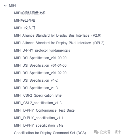

Click “Read the Original” to access the download of the protocol source files.