#01MIPI A-PHY Background Introduction
As an emerging ultra-high-speed wired data transmission method for in-vehicle applications, MIPI A-PHY is a high-speed serializer-deserializer (SerDes) physical layer interface specification designed specifically for automotive applications, aimed at meeting the automotive industry’s demand for high-performance, long-distance communication. The primary feature of this technology is its high speed, followed by reliability, intended to handle the increasing data flow within vehicles, especially the massive video streams and point cloud data from autonomous driving sensors.
It is the first standardized, asymmetric, long-distance specification developed by the MIPI Alliance (Mobile Industry Processor Interface Alliance) for advanced driver assistance systems (ADAS), autonomous driving systems (ADS), infotainment displays, and other sensor applications.
The so-called SerDes divides the signal source into smaller data blocks, which are transmitted serially and then reassembled into complete parallel data at the receiving end. This method is fundamentally similar to the TCP/IP protocol.
Serial transmission is superior to parallel transmission in certain scenarios because parallel transmission requires consideration of complex synchronization and timing issues, which increase with the number of parallel lines. Additionally, from an electrical perspective, multiple signal lines are prone to crosstalk, and the wiring layout requires high skill to avoid interference. Moreover, simply put, the more signal lines there are, the greater the chance of failure or disconnection of any one line, making troubleshooting difficult among multiple lines.
Any cable communication system that meets the MIPI A-PHY hardware specifications can be referred to as a MIPI A-PHY product, especially codec chipsets, with the current main supplier list as follows:
|
Company Name |
Nationality/Region |
Product/Contribution |
|
Valens Semiconductor |
Israel |
MIPI A-PHY technology leader, launched the first VA7000 series chipset compliant with MIPI A-PHY standards, suitable for ADAS and autonomous driving |
|
Analogix Semiconductor |
USA |
Provides MIPI A-PHY compatible SerDes chipsets, completing interoperability testing |
|
Hosiden |
Japan |
Supplier of harnesses, connectors, and components, supporting the MIPI A-PHY ecosystem |
|
Sumitomo Electric |
Japan |
Participates in the construction of the MIPI A-PHY ecosystem, providing related support |
|
LG Innotek |
South Korea |
Develops and produces MIPI A-PHY chip modules, driving the development of in-vehicle connectivity technology |
|
Black Sesame Intelligent Technology Co., Ltd. |
China |
Plans to adopt the VA7000 chipset, supporting A-PHY connection standards |
|
Yutai Microelectronics |
China |
Currently developing MIPI A-PHY related products, supporting domestic and international intelligent driving platforms |
|
Chipset Technology |
China |
Launches innovative MIPI A-PHY SerDes chipsets, supporting high-speed data transmission |
|
Shou Chuan Microelectronics |
China |
MIPI A-PHY ecosystem member, completed interoperability testing |
|
Intel |
USA |
Implements MIPI A-PHY standards through foundry services, collaborating with Valens to develop automotive technology |
|
OmniVision Technologies |
USA |
Provides MIPI A-PHY compatible cameras for advanced driver assistance systems |
Table 1 MIPI A-PHY Major Suppliers
Not surprisingly, the most important components in MIPI A-PHY are the codec chipsets, which are the main devices for data transmission rates and error correction. Additionally, besides manufacturers specializing in harness cable chipsets, Black Sesame, which focuses on autonomous driving, is also involved, as the primary application of MIPI A-PHY is in autonomous driving and intelligent cockpit.
MIPI A-PHY is a wired communication method, not a wireless one, because wired communication is more reliable and resistant to interference than wireless. The term long-distance refers to the length of the in-vehicle harness, which can reach up to 15 meters, sufficient for general vehicles.
Its main features are as follows:
MIPI A-PHY provides an extremely low packet error rate (10^-19), which means that data transmission errors are almost nonexistent throughout the vehicle’s lifespan. The data rate supports up to several tens of Gbps per second, capable of meeting the high bandwidth requirements of applications in modern vehicles, such as connections for high-definition cameras and displays.MIPI A-PHY offers point-to-point or daisy-chain topologies, supporting high-speed unidirectional data transmission and embedded bidirectional control data transmission, optimizing the design of complex in-vehicle networks.
Finally, compared to traditional short-distance interfaces (such as D-PHY and C-PHY, which are used for mobile devices like smartphones and tablets), A-PHY supports cable transmission of up to 15 meters, making it very suitable for long-distance communication needs within vehicles. During transmission, signals are affected by resistance, capacitance, and inductance, leading to a gradual weakening of signal strength, so signal strength and quality will degrade with the length of the harness, a phenomenon known as signal attenuation, typically measured in dB. Therefore, 15 meters is already a considerable distance.
Readers may find in daily life that, for example, mobile phones, excessively long data cables (charging cables) perform poorly. A 2-meter cable, while convenient for a larger range of motion, does not transmit data as efficiently as a 1-meter or half-meter cable. According to experimental data, the data transmission efficiency of a 1-meter cable is significantly better than that of a 2-meter cable, while a 0.5-meter cable performs even better than a 1-meter cable.
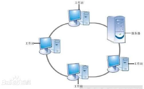
Figure 1 Daisy-chain topology diagram, from Baidu Encyclopedia, closed is a ring topology, open is a chain topology
The application fields are mainly scenarios with large data traffic
a, autonomous driving and advanced driver assistance systems (ADAS/ADS):
MIPI A-PHY plays a key role in ADAS/ADS systems, connecting image sensors, radar, and other perception devices to the central processing unit (ECU), ensuring real-time and reliable data transmission.
b, intelligent cockpit, HMI, infotainment systems:
It can efficiently transmit video streams from the host to multiple displays, supporting high-quality in-vehicle entertainment experiences. .
c, in-vehicle monitoring systems:
MIPI A-PHY ’s high reliability and long-distance characteristics allow it to connect various corners of the vehicle, making it an ideal choice for in-vehicle monitoring systems, such as driver status monitoring and passenger safety monitoring, as well as cargo security.
Next, the working architecture of MIPI A-PHY is introduced as follows:
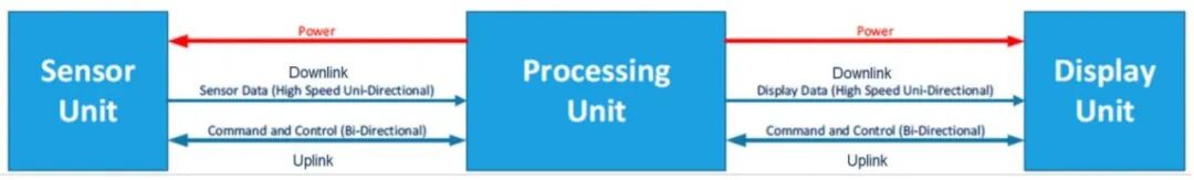
Figure 2 MIPI A-PHY working architecture diagram, including data transmission and power, image from STMicroelectronics
MIPI A-PHY uses coaxial cables or differential pairs to transmit signals.
It is bidirectional, not only used for data transmission but also can power external devices through the data line, a technology commonly seen in hard drives and mobile devices.
The downlink (High-Speed Downlink) is mainly responsible for transmitting high-speed data streams. It supports the data transmission needs of high-resolution cameras, image sensors, and display devices, such as supporting multiple 4K resolution devices.
The uplink (Uplink) is used for transmitting command and control data. Therefore, the uplink bandwidth is lower, supporting a maximum of 200 Mbps, but it is also more than twice the rate of high-speed CAN.
A-PHY has two profiles:
Profile 1:
-
Objective: Suitable for applications requiring lower downlink speeds and lower hardware complexity.
-
Technical Basis: Based on NRZ (Non-Return-to-Zero) and 8B/10B encoding technologies.
-
Features: Lower cost, suitable for scenarios with less demanding performance requirements.
Profile 2:
-
Objective: Suitable for applications requiring higher downlink speeds and stronger noise immunity.
-
Technical Basis: Based on PAM (Pulse Amplitude Modulation) technology.
-
Features: Higher bandwidth utilization, more suitable for high-performance scenarios, such as in-vehicle cameras or high-end display devices.
#02
Electrical Overstress (EOS) Test EOS test
MIPI A-PHY’s EOS (Electrical Overstress) testing is designed to ensure the robustness and reliability of electronic modules in automotive applications when faced with voltages or currents exceeding their design specifications. This testing simulates various electrical anomalies that may occur in the vehicle environment, such as electrostatic discharge (ESD) events caused by human contact or internal system failures.
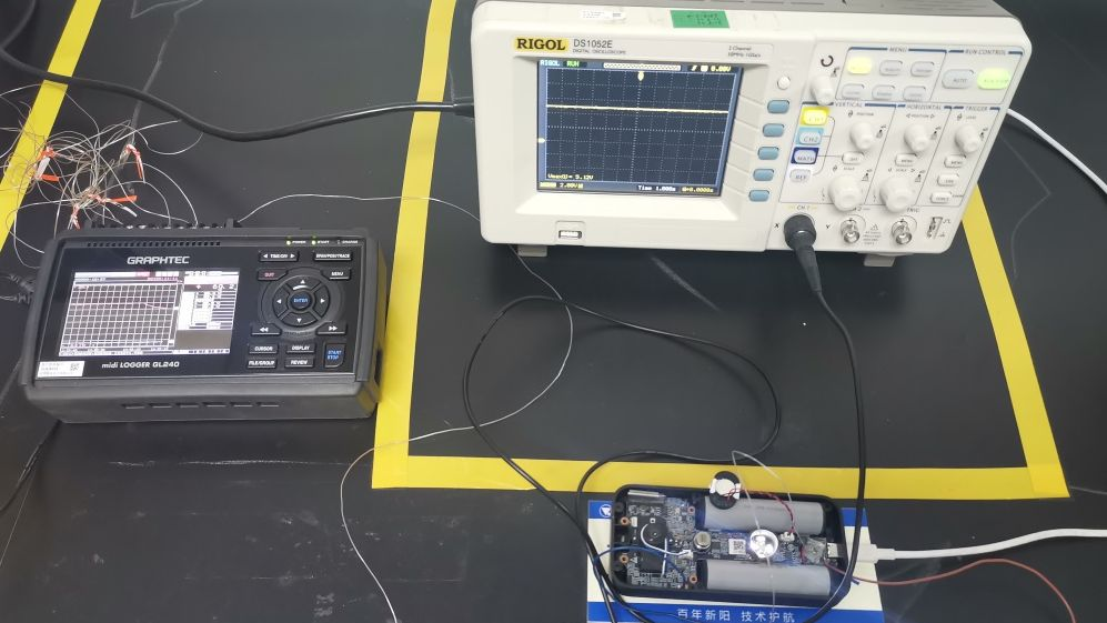
Figure 3 EOS testing scenario, simulating electrical surges, overvoltage, and overcurrent scenarios, image fromCSDN
In automotive applications, especially those involving high-bandwidth data transmission (such as ADAS, ADS, and surrounding sensors), EOS protection is crucial for autonomous driving safety. This is because the automotive environment is typically more complex and harsh than consumer electronics, potentially facing a wider range of temperature variations, vibrations, and other electrical interferences. Therefore, conducting EOS testing on the MIPI A-PHY interface helps verify its durability under actual usage conditions.
EOS testing typically includes the following types:
-
Surge Testing: Simulates high-voltage pulses caused by lightning strikes or other power transients.
-
Short Circuit Testing: Assesses the device’s performance under extreme conditions (such as accidental short circuits).
-
Overvoltage/Overcurrent Testing: Checks whether the device can operate under voltages or currents above the normal operating range without damage.
These tests are typically conducted according to international standards (such as IEC 61000-4 series) to ensure consistency and repeatability of results.
For in-vehicle cable data transmission systems that comply with the MIPI A-PHY hardware interface specifications, EOS testing simulates electrical risks to test various impacts on such systems, primarily rate degradation, data loss, or errors, etc.
#03
Main Electrical Risks in the In-Vehicle Environment
The automotive environment presents numerous sources of electrical risks, including but not limited to electromagnetic interference and electrostatic discharge. Ignition systems, relay contacts, AC generators, injectors, and other accessories, as well as the discharge of static electricity accumulated by the human body, can not only cause such hazards but also trigger other electrical disturbances. These hazards can affect both data lines and power lines. The following content mainly discusses the electrical risks faced by data lines, as MIPI A-PHY is used for data transmission.
The transient phenomena occurring on data lines are primarily ESD surges (Electrostatic Discharge, abbreviated as ESD). This surge is also the reason for the electric shock experienced when a person, after wearing a wool sweater in winter, touches a doorknob. Its characteristics include low energy but a very high rate of voltage change dv/dt, which can generate a strong electromagnetic field.ISO 10605 and IEC 61000-4-2 standards define ESD surges. The data lines involved include communication lines: media transmission lines, video links, data buses, sensor data lines, etc. The following diagram illustrates the hazardous surge waveforms that may occur on data lines.
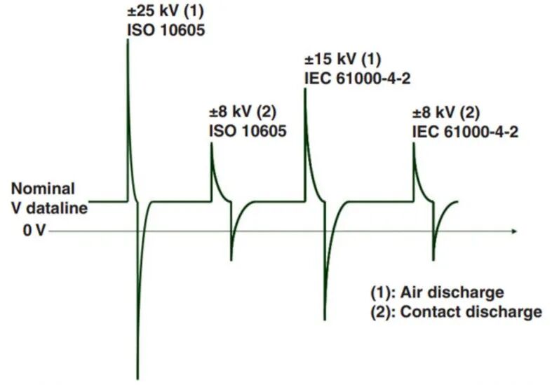
Figure 4 Electrostatic discharge surge in data lines, image from STMicroelectronics public materials
Firstly, the discharge voltage is extremely high, measured in kilovolts; secondly, the instantaneous voltage of air breakdown is much lower than that of contact discharge, less than one-third, but can still reach positive and negative 8kV.
The impact of electrostatic discharge (ESD) surges on MIPI A-PHY cables has several serious effects.
1. Data Loss or Corruption: Even low-frequency ESD can propagate through tightly wound cables, causing data loss or physical damage via Ethernet ports. For MIPI A-PHY, this may lead to critical automotive data transmission errors or interruptions.
2. System Performance Degradation: ESD events may lead to performance degradation of MIPI A-PHY systems, manifested as increased latency, reduced throughput, and overall communication efficiency decline. This impact may stem from slight damage to cables and interface components due to ESD.
3. Hardware Damage: Severe ESD surges can cause permanent hardware damage to MIPI A-PHY cables and their connected devices. ESD can lead to peak voltages of up to 25kV, with a total pulse width of about 100 ns, which is particularly dangerous for embedded FET gates.
4. Increased Electromagnetic Interference (EMI): ESD events may exacerbate electromagnetic interference, affecting the normal operation of other electronic devices surrounding MIPI A-PHY cables. This is not limited to directly connected devices but may also impact adjacent systems.
5. Long-term Reliability Issues: Although a one-time ESD event may not immediately cause failure, it may weaken the long-term reliability of MIPI A-PHY cables and related components, especially in automotive applications where these systems need to maintain stable performance throughout the vehicle’s lifespan.
To mitigate these impacts, designers typically adopt specialized ESD protection measures. Therefore, we need to use the EOS testing in the second section to compare the effects of scenarios with and without protection.
#04
Protection Measures and Effects
First, let’s introduce the A-PHY cable topology, as the ESD protection measures are closely related to the cable structure:
A-PHY primarily supports three types of cables to accommodate different application scenarios and requirements.
a, Unbalanced Coaxial Cable: Traditional coaxial cables, widely used in various scenarios.

Figure 6 Unbalanced coaxial cable, image from the internet
Unbalanced coaxial cable (Unbalanced Coaxial Cable) refers to a type of cable with asymmetric impedance characteristics between the signal conductor and ground. Coaxial cables consist of a central conductor surrounded by an outer shielding layer, separated by insulating material. This structure defines coaxial cables as unbalanced lines because the signal conductor is a small solid wire, while the ground is a woven metal layer surrounding the inner signal wire and insulation. The central conductor is responsible for almost all current and signal voltage transmission, while the shielding layer primarily prevents external electromagnetic interference and is usually connected to electrical ground.
Unbalanced coaxial cables are used in applications requiring good shielding effects, such as broadcasting, television, RF signal transmission, and high data flow within vehicles.
b, Shielded Differential Pair (SDP): A type of balanced cable with good anti-interference capabilities.

Figure 7 SDP Cable
Differential signals refer to sending two equal amplitude but phase-opposite signals over two conductors. The receiving end determines the logic state of “0” or “1” by comparing the voltage difference between these two signals. This method significantly improves anti-interference capabilities because common-mode interference produces the same voltage changes on both conductors, which differential receivers will ignore. The core of SDP is to use a metal shielding layer to wrap a pair of differential signal lines to transmit signals. This shielding layer can be made of aluminum foil, copper foil, or other conductive materials, aiming to isolate external electromagnetic fields from internal signal lines.
c, Star Quad Cable (STQ): Composed of four conductors, divided into two pairs of differential pairs, suitable for high-performance applications.
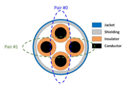
Figure 8 Star Quad Cable
The internal four conductors of the star quad cable are evenly distributed, forming a center-symmetric star structure. This layout helps reduce electromagnetic interference and effectively lowers crosstalk between lines. .
The reason for explaining these cable and interface types is that they are related to ESD protection measures.
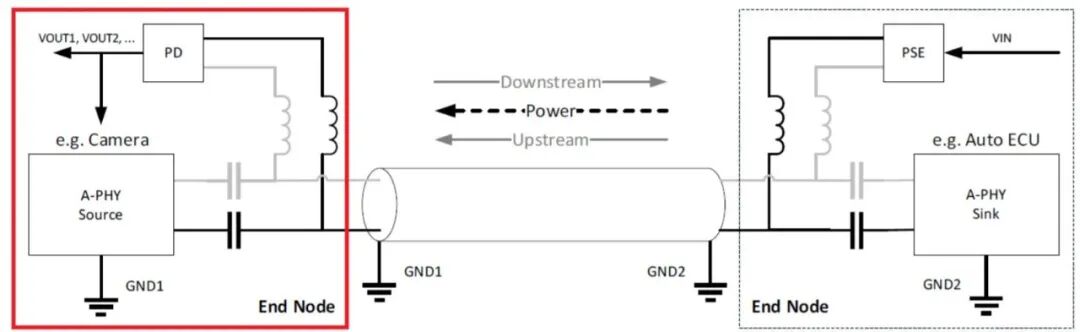
Figure 9 A-PHY System Connection from Source to Sink, from STMicroelectronics documentation
The cable that carries both uplink and downlink flows and power is one of the aforementioned three types of cables. The total of all electronic devices passed between the source and sink is referred to as a complete TLIS, including PCBs, cables, and A-PHY processing chips.
TLIS refers to Transmission-Line Interconnect Structure, which describes the physical path or medium through which signals are transmitted between the transmitter and receiver. This structure may include multiple cascaded transmission line segments, such as printed circuit boards, flexible circuit boards, interconnect connectors, and cable components. In the MIPI A-PHY standard, the characteristics of TLIS are defined for specific topologies, such as coaxial topology, where the total length of coaxial cables can reach up to 15 meters and include up to 4 inline connectors, with a minimum cable segment length of 30 centimeters.
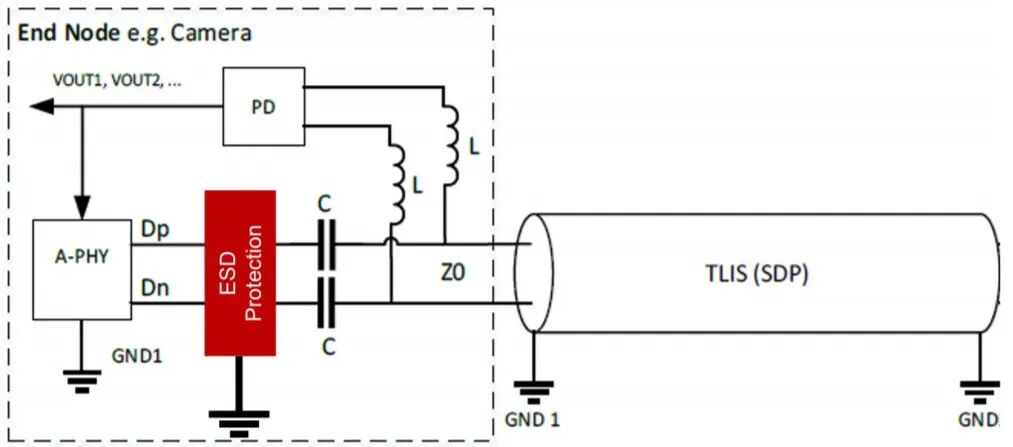
Figure 10 Adding ESD protection devices to the A-PHY system
STMicroelectronics introduces a specific ESD protection device, a very compact device called ESDAXLC6-1BT2Y, which is a diode.
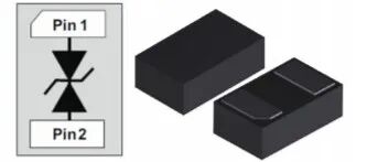
Figure 11 ESD Protection Device: ESDAXLC6-1BT2Y, from STMicroelectronics
This is essentially a bidirectional TVS (Transient Voltage Suppressor) diode that can provide protection against overvoltage events in both positive and negative directions. Under normal operating conditions, it behaves as a high-impedance state, having almost no impact on the normal operation of the circuit. However, when the circuit is subjected to ESD transient voltage spikes, the TVS diode quickly conducts and reduces impedance, directing excess current to ground, thereby limiting voltage rise and protecting sensitive components in subsequent circuits from damage. For positive or negative ESD pulses, it effectively reduces them to a safe voltage range, ensuring that the protected circuit is not damaged by excessively high or low voltages.
To understand this with a familiar concept, it acts as a filter, filtering out instantaneous high-voltage surges by allowing the surge to break down the diode, conducting it to the ground.
So how effective is the use of this device? The following signal eye diagram comparisons are provided:
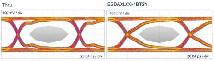
Figure 12 Signal eye diagram with and without using ESDAXLC6-1BT2Y, left is through (thru), which means not using it, and the right is using it, from STMicroelectronics documentation
The intuitive rule for assessing the quality of an eye diagram is to look at how wide and round the eye is; the larger and rounder, the better. The more open the eye diagram, the greater the allowable error for noise and jitter, indicating better system performance..
If the phrase “how wide and round” is not intuitive enough, a more specific equivalent statement is to look at the distance between the upper and lower eye lines; the farther apart, the better.
In the left sub-diagram of Figure 12, please note the left side of the eye, which clearly shows a dent, indicating a decline in data transmission quality, further suggesting that ESD protection is effective, as the right side eye diagram with protection does not exhibit this denting phenomenon.
#05
Explanation and Summary
This article primarily draws information from STMicroelectronics documentation titled MIPI A-PHY EOS protection in automotive application, in addition to detailing the background and applications of MIPI A-PHY, and supplementing some evaluation methods and metrics for better reader understanding.
MIPI A-PHY has recently been regarded as the most promising solution to address the massive and continuously growing data transmission issues in autonomous driving and intelligent cockpits, thus attracting significant attention, with numerous manufacturers both domestically and internationally following suit. Below is a comparison with in-vehicle Ethernet and the CAN bus.
|
Technology |
Data Transmission Rate |
Applicable Scope |
Cost Factors |
|
MIPI A-PHY |
Up to48 Gbps |
Autonomous driving, ADAS, camera sensor links, audio and video entertainment |
Initial development costs are high, but long-term savings on BOM costshttps://resources.altium.com.cn/p/whats-in-the-mipi-a-phy-automotive-serdes-specification |
|
In-vehicle Ethernet |
Currently reported1G-10G, with future developments |
Complex infotainment systems, domain controller interconnections (domain control and gateway interconnections) |
Reduces harness and lowers costs, but wiring complexity must be consideredhttps://www.eeworld.com.cn/qcdz/eic681181.html |
|
CAN Bus |
Maximum about1 Mbps |
Communication between functional modules such as engine control, lighting switches, etc. |
Simple and inexpensive to implement, but inefficient for large data volume transmissionhttp://www.cntransun.com/home/news/id/999 |
At least in terms of rate, MIPI A-PHY is a strong competitor to in-vehicle Ethernet, and if it can further prove itself in terms of anti-interference and cost-effectiveness, it may become one of the next-generation mainstream in-vehicle data transmission solutions in the fields of ADS/ADAS autonomous driving and intelligent cockpit HMI.