The degree of electronicization in automobiles is an important indicator of modern automotive standards, and the advancement of automotive electronic technology has also driven the development of bus technologies. Traditional automotive electronics use point-to-point communication methods, with no connections between units, resulting in the need for massive wiring harness systems for the entire vehicle. From both spatial layout and communication efficiency perspectives, traditional electrical networks cannot meet the requirements of modern vehicles. Furthermore, various ECU units in modern vehicles constantly exchange data, such as engine speed, throttle position, and vehicle speed, necessitating the integration of all nodes into a bus network to achieve information sharing. Due to the varying real-time communication requirements of each electronic unit, modern automotive networks based on multi-bus technologies have emerged.
LIN is a bus technology proposed by five vehicle manufacturers (Audi, BMW, Chrysler, Volvo, and Volkswagen), one semiconductor manufacturer (Freescale), and one tool provider (Mentor Graphics). The introduction of the LIN bus can reduce the manufacturing costs of controllers in vehicles without affecting the normal operation of the entire in-vehicle network. LIN bus adopts the universal asynchronous reception/transmission standard, with a single master and multiple slaves structure, where the entire network has only one master node and several slave nodes, making it a single-wire bus communication system.
LIN bus is a single master and multiple slave organization system without a bus arbitration mechanism. LIN bus has the following characteristics:
1. LIN bus has a relatively low communication rate, generally with a maximum rate of 20 Kbit/s, but it can meet low-speed communication needs;
2. It uses serial communication, typically employing single-wire transmission, saving transmission harnesses and enabling long transmission distances;
3. LIN communication interface hardware is based on SCI/UART general interfaces, making it inexpensive and cost-effective;
4. The master node can schedule the entire network, so arbitration is unnecessary;
5. The number of nodes can be increased or decreased at any time, but there can be a maximum of 16 nodes; it supports diagnostic functions and multiple message transmissions.
LIN bus is a single master and multiple slave structure bus, meaning there can only be one master node in the entire network, but multiple slave nodes can exist. The following diagram shows the LIN network topology.
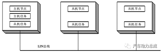
As shown in the diagram, the master node not only has master tasks but also slave tasks, while the slave nodes only have slave tasks. In LIN bus network communication, the scheduling of message frames is accomplished through a scheduling table, which can determine the sending timing and time slots for each message frame. The sending timing refers to the order in which each message is sent across the entire network, while the sending time slot refers to the time reserved for sending that message. Generally, different messages may have different sending time slots.
During the design phase of LIN network nodes, it is necessary to design the scheduling table, which makes LIN bus communication predictable. Furthermore, the master node can have multiple scheduling tables to prevent a single scheduling table from potentially causing network instability; switching between multiple scheduling tables can ensure communication reliability.
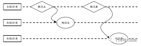
Typically, every frame header sent by the master node will be received by the slave nodes, but the slave nodes will decide whether to accept data, send data, or remain idle based on the identifier of the frame header. The following diagram illustrates the LIN message communication principle.
CAN (Controller Area Network) is a network used for monitoring and controlling various devices. CAN was originally designed by the German company Bosch for automotive monitoring and control systems. CAN has unique design features and extremely high reliability, with strong field interference resistance. Its basic characteristics are as follows:
1. Simple structure, only two wires connected to the outside, and includes error detection and management modules;
2. Flexible communication method. It can operate in a multi-master mode, where any node in the network can actively send information to other nodes at any time, regardless of master or slave;
3. It can send and receive data in point-to-point, point-to-multipoint, and global broadcast modes;
4. Node information on the network can be divided into different priority levels to meet various real-time requirements;
5. CAN communication format adopts a short frame format, with a maximum of 8 bytes per frame, which can meet the general requirements for control commands, working status, and test data in typical industrial control fields. At the same time, 8 bytes will not occupy too much bus time, thus ensuring communication real-time performance;
6. CAN adopts a non-destructive bus arbitration technology. When two nodes send data to the bus simultaneously, the node with lower priority actively stops sending data, while the node with higher priority can continue sending data without being affected, greatly saving arbitration conflict time and preventing network paralysis even under heavy load;
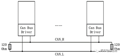
7. The maximum direct communication distance can reach 10 km (speed skb/s), and the maximum communication speed can reach 1 Mb/s (at this time the longest distance is 40 m). There can be up to 110 nodes, and the communication media can be twisted pair, coaxial cable, or optical fiber;
8. The CAN bus communication interface integrates the physical layer and data link layer functions of the CAN protocol, completing framing processing for communication data, including bit stuffing, data block encoding, cyclic redundancy check, priority determination, and other tasks;
9. CAN bus adopts CRC parity check and can provide corresponding error handling functions, ensuring the reliability of data communication.
CAN bus protocol corresponds to the data link layer in the ISO/OSI reference model, meeting the real-time control needs of automatic devices. It has been established as an international standard.
CAN bus uses differential signaling to send and receive messages, providing good interference resistance.
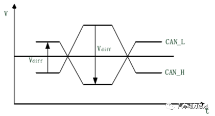
As shown in the diagram, the high level of the differential signal is represented by CAN_H, with a voltage of 3.5 V; the low level is represented by CAN_L, with a voltage of 1.5 V; when CAN_H and CAN_L stabilize at the average level of the bus, Vdiff approaches 0, indicating an invisible state; when Vdiff exceeds a certain minimum threshold of differential voltage, it indicates a visible state. When the visible state occurs, it will override the previous invisible state on the bus.
The German company Bosch released the CAN FD (CAN with Flexible Data-Rate) version 1.1 in 2011. As an upgrade to the CAN bus, CAN FD significantly increases bandwidth to 10 Mbps and improves the error checking mechanism. Meanwhile, CAN FD retains the characteristics of the CAN bus, maintaining the same physical layer, and has a similar controller interface to the CAN bus, allowing for replacement without significant modifications at the software level, thereby reducing development cycles and costs.
CAN bus has been widely used in in-vehicle communication and is considered one of the most reliable methods for transmitting real-time data. The CAN protocol determines the priority of each message being sent, allowing for simple and uninterrupted communication flow. However, the CAN bus also has limitations; the baud rate of the CAN bus is inversely proportional to the bus length, so the transmission distance cannot be too long while ensuring transmission speed (in addition, the data length is limited over time). CAN FD increases the bit rate in the data section, allowing for an increase in the number of bytes in the data section without extending the length of the CAN frame time.
Another pressing reason for transitioning from CAN bus to CAN FD bus is the safety of automotive systems. CAN generally operates within closed systems and cannot be accessed externally, but the wave of intelligent connectivity is turning vehicles into open systems, making information security increasingly critical. CAN FD can have up to 64 data bytes in one frame, providing ample space for security signatures. As CAN FD technology begins to appear in mid-to-high-end microcontrollers, built-in hardware supports security algorithms such as the Advanced Encryption Standard (AES), which will be widely used in automotive environments.
CAN FD frame structure is divided into seven parts: frame start, arbitration field, control field, data field, CRC check field, ACK acknowledgment field, and frame end. Compared to CAN, the CAN FD frame structure removes support for remote frames and adds three bits in the control field: EDL (Flexible Data Rate Format), BRS (Bit Rate Switch), and ESI (Error State Indicator). The arbitration segment baud rate is consistent with traditional CAN, reaching a maximum of 1 Mbps, including the SOF bit through to the BRS bit, as well as the ACK field and frame end segment. The baud rate of the data segment can reach up to 5 Mbps, including the ESI bit through to the CRC field. The standard frame structure of CAN FD is shown in the following diagram.
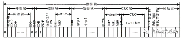
FDF frame structure: used to distinguish whether it is a traditional CAN frame or a CAN FD frame, the implicit bit 1 indicates a CAN FD frame, while the explicit bit 0 indicates a CAN frame.
BRS bit rate switch: indicates whether the message from the control field BRS bit to the end of the CRC check field changes speed, with the implicit bit 1 indicating a change in speed, and the explicit bit 0 indicating no change in speed.
ESI error state indicator: used to indicate the current state of the node, with the explicit bit (dominant bit) 0 indicating an active error state, and the implicit bit (recessive bit) 1 indicating a passive error state.
CAN FD inherits the shortcomings of the CAN protocol in terms of safety; once the CAN FD bus is compromised, the vehicle faces the threat of being controlled. The following lists the deficiencies of the CAN FD protocol:
1. Lack of security protection protocols: ISO 11898 (2015) published the CAN FD physical layer and data link layer protocols, which do not address security aspects. Data transmission between CAN FD nodes is conducted in plaintext, making it easy for outsiders to deduce linear patterns from a large number of CAN FD messages and obtain the real data of both communication parties;
2. Broadcast-based communication method: The entire vehicle CAN FD network is formed by various nodes, all connected to a single CAN FD bus. Once a node sends a message, all other nodes can receive it. Utilizing this characteristic, as long as one connects to the CAN FD bus, one can listen to all communications between nodes, lacking privacy protection;
3.ID priority arbitration mechanism: When multiple CAN FD messages are active on the bus simultaneously, the ID priority arbitration avoids bus conflicts. The lower the ID, the higher the priority, and lower priority must wait for higher priority to finish before sending. This allows attackers to continuously send high-priority messages, making it difficult for low-priority messages to be sent, achieving denial of service communication;
4. Lack of message source authentication: CAN FD does not label the addresses of each node, only encoding data through message identifiers (ID numbers). It is difficult to ascertain which node is the message source; therefore, if a node is hijacked, it can spoof other nodes’ transmissions, and the receiver lacks a corresponding mechanism for authenticating the message source.
In 1996, Mercedes, based on its D2B system, began discussions about MOST with BMW and SMSC, deciding to jointly develop it with other car manufacturers. In 1998, BMW, Mercedes, Buick, and SMSC established the MOST cooperation organization as a German civil partnership, and soon Audi joined the organization. After its establishment, the MOST cooperation organization focused on rapid standardization of protocols and quickly implemented actual systems in vehicles (however, this technology is merely a product of cooperation in the automotive industry and does not possess formal standards).
MOST (Media Oriented System Transport) is a multimedia transmission system bus, representing a “multimedia transmission system.” It is a network technology for multimedia information transmission in vehicles based on communication protocols, using optical fibers or twisted pairs as physical transmission media, specifically developed for in-vehicle applications to serve multimedia.
MOST bus has the following characteristics:
1. Currently, 140 vehicle models utilize MOST network technology. It is the mainstream entertainment media transmission technology, having released three generations of MOST network technology specifications, with mature technology. The next generation network bandwidth can reach 1~5 Gbps, and is currently under development.
2. MOST bus consists of one time master node and several time slave nodes, transmitting clock signals along with data signals. There can be a maximum of 64 nodes in this network, with a maximum distance of 10 meters between nodes.
3. Compared to traditional in-vehicle infotainment system solutions, it uses less and lighter wiring harnesses, has stronger electromagnetic interference resistance, and allows for easier addition and deletion of applications.
4. Specifically designed to meet the stringent requirements of in-vehicle environments, the new optical fiber-based network can support 24.8 Mbps data rates, offering advantages over previous copper cables by reducing weight and minimizing electromagnetic interference (EMI), while also supporting plug-and-play mechanisms.
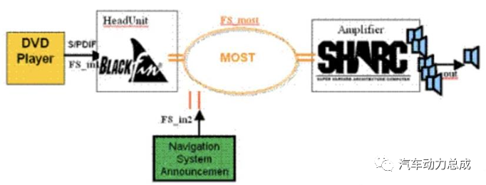
MOST bus transmits data using optical pulses, adopting a ring structure, where data can only be transmitted in one direction within the ring bus. The transmission technology of MOST is similar to that of the Public Switched Telephone Network (PSTN), with defined designs for data channels and control channels. The control channel is used to set how to use the channels for data transmission and reception. Once set, data continuously flows from the sender to the receiver without further packet processing, making this operational mechanism ideal for real-time audio and video streaming transmission.
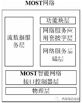
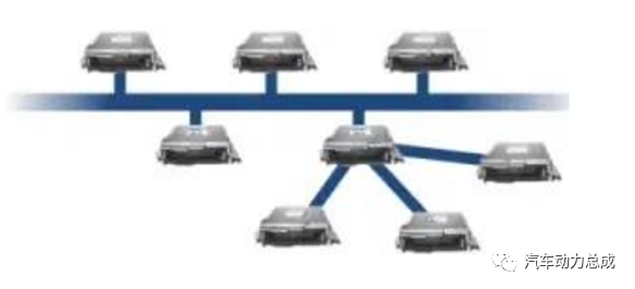
MOST completely adheres to the ISO/OSI seven-layer data communication protocol reference model, and in terms of network connection, it adopts a ring topology. However, for more stringent requirements in transmission control applications, MOST also allows for star (also known as radial) or double-ring connection configurations.
MOST intelligent network interface controllers are mainly responsible for socket management, intelligent device management, network protection mode settings, and hardware watchdog timer settings. The physical layer consists of optical and electrical physical layers, allowing MOST network signals to be transmitted over optical fibers or twisted pairs. In the MOST network, frames are the basic unit of data transmission, and each frame is divided into three data fields, used for transmitting control bytes, streaming data, and asynchronous data. Because data frames are sent at fixed intervals, the frequency is 44.1 KHz or 48 KHz. Thus, the same data fields of adjacent data frames in the network form continuous channels for transmitting corresponding information, namely control channel, streaming data channel, and asynchronous data channel.
Due to its focus on some core requirements of the automotive industry, including faster data rates, more flexible data communication, more comprehensive topology options, and fault tolerance, FlexRay can provide the speed and reliability needed for next-generation in-vehicle control systems.
FlexRay bus technology has the following features:
1. It has the advantage of high bandwidth; the maximum performance limit of the CAN network is 1 Mbps, while the maximum performance limit of the LIN and K-LINE branch networks is 20 Kbit/s; whereas the data rate on both channels of FlexRay can reach a maximum of 10 Mbps, with a total data rate of up to 20 Mbit/s, making the network bandwidth of FlexRay potentially 20 times that of CAN.
2. It has redundancy communication capabilities, allowing for complete replication of network configurations through hardware, progress monitoring, and flexible configurations that support various topologies, such as bus, star, and hybrid topologies. Designers can configure distributed systems by combining two or more of these topologies.
3. It can perform synchronous (real-time) and asynchronous data transmission to meet the needs of various systems within the vehicle, providing static and dynamic communication segments within each communication cycle. The fixed-length static segment of the FlexRay frame is transmitted using a fixed-time-trigger method, while the dynamic segment uses a flexible time-trigger method.
4. It operates on a cyclic basis, with a complete communication cycle consisting of static segments, dynamic segments, symbol windows, and network idle time;
5. It is based on a time-triggered transmission method, where each node is allocated its own time slot, and each application node sends messages at the arrival of its time slot and knows when to receive its own messages.
FlexRay data frames consist of three parts: the start segment, payload segment, and end segment. As shown in the diagram, when the data frame is transmitted on the bus, messages from the controller’s internal transmission queue are transmitted sequentially from left to right, starting with the start segment bytes, followed by the payload segment bytes, and finally the end segment bytes. The completion of the transmission of all three parts represents the completion of a complete FlexRay data frame transmission.
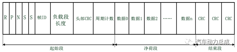
The start segment (Playload segment) occupies 5 bytes of data length, which is pre-defined, consisting of the following parts:
R: Reserved bit (1 bit), reserved for future protocol expansion. When it is the sending node, this bit is set to zero; if it is the receiving node, this bit can be ignored.
P: Valid payload pre-indicator bit (1 bit), indicating whether the payload data segment of the sent data frame contains an optional vector. For example: 1 means included, 0 means not included.
N: Empty frame (invalid frame) indicator bit (1 bit), indicating whether the data frame is an empty frame; even if there is no valid data in the empty frame, the receiving node will still use the relevant information in the empty frame. When it is 1, it indicates that the frame is an empty or invalid frame; 0 indicates a valid frame.
Two consecutive S bits: The first S is the synchronization frame indicator bit, which indicates whether the frame is a synchronization frame (1 indicates a synchronization frame, 0 indicates a non-synchronization frame). The second S is the start frame indicator bit, which indicates whether it is a start frame (1 indicates a start frame, 0 indicates not a start frame). When a frame’s start frame indicator bit is set to 1, its synchronization frame indicator bit should also be set to 1.
Frame ID (11 bits): The time slot number, determining in which time slot the data frame will be transmitted. In one communication cycle, the frame ID can only appear once, used to set when the frame can be sent in which time slot, with a range of 1-2047; 0 is not a valid frame identifier.
Valid payload data length (7 bits): The range is 0-127, used to indicate the size of the valid payload data segment. In any communication cycle, if the transmitted message frame is a static frame, the valid payload data length is fixed and the same; if it is a dynamic frame, the valid payload data length can vary based on actual needs.
Frame header CRC (11 bits): Contains a cyclic redundancy check code calculated based on the synchronization frame indicator bit, frame ID, and valid payload data length. When the node sends the frame header CRC, the check bits are sent in order of importance.
Frame count cycle (6 bits): Used to indicate in which of the 0-63 communication cycles the data frame is sent. The sending node writes the node cycle count into the frame cycle count, selecting the information to be sent; the receiving node selectively receives based on the frame cycle count.
Valid payload data segment (Playload segment): Used to store the data information to be transmitted, with a size between 0-254 bytes. In the static segment transmission, the first 0-12 bytes of the message frame’s valid payload data segment can be used as the network management vector, indicated in advance by the valid payload pre-indicator bit (P) in the start segment. In dynamic segment transmission, the length of the valid payload data segment is uncertain, with the first few bytes being the message identifier (ID), written in as application data by the sending node, while the communication controller does not participate; the receiving node identifies the message through the ID filter.
End segment: Composed of a 24 bit frame CRC. The CRC polynomial calculation can verify whether the data in the start segment and valid payload data segment is correct. This process verifies all fields in the start segment and payload segment.
In the FlexRay protocol, it is stipulated that FlexRay communication occurs in a cyclic manner. Since it is based on a time-triggered transmission method, each node is allocated its own time slot, and each application node sends messages at the arrival of its time slot and knows when to receive its own messages. This requires system description parameters—such as baud rate, number of time slots, time slot length, and message allocation for static and dynamic segments—which will be defined during system initialization. The time slot allocation diagram for FlexRay is shown in the following diagram.
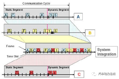
The static segment of the communication cycle consists of multiple static time slots, all of which have the same length and are fixed in configuration, numbered sequentially starting from 1. The static segment uses Time Division Multiple Access (TDMA) technology, where a pre-designed scheduling table in the microprocessor assigns messages to fixed time slots. When the time slot for a message arrives, that message can be transmitted. The time slot is the smallest time unit in the static segment. Before communication begins, the messages to be transmitted in the FlexRay network are planned as a whole, with each node assigned a certain number of time slots. During communication, the time slots corresponding to nodes cannot be modified. When planning the entire communication network, it is important to reasonably allocate the messages transmitted in the static segment, without exceeding the maximum length the static segment can handle. Therefore, even if the vehicle operates in external interference and harsh environments, data transmission based on the FlexRay protocol can minimize information jitter and delay. The communication method for the FlexRay static segment is shown in the following diagram.
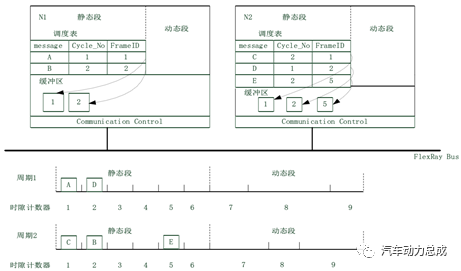
In the dynamic segment of the communication cycle, the allocated time slot length is not fixed; the length of the allocated time slots changes based on the size of the data frame, enhancing data transmission flexibility. The dynamic segment uses a Flexible Time Division Multiple Access (FTDMA) technology, where the minimum time unit is subdivided from the time slot into micro time slots, making it more flexible than TDMA, suitable for transmitting frames with uncertain timing. When the transmitted frame’s ID corresponds to the time slot number, the node will send the data in the buffer; if no nodes need to transmit data, after a micro time slot’s duration, each node’s time slot counter will increment by 1. The dynamic segment is based on an event-triggered transmission method, with messages transmitted in the dynamic segment having varying priority levels. Important and urgent information should be placed in lower-numbered time slots to ensure these messages have transmission opportunities in each cycle.
FlexRay features are well-suited for real-time control functions. Thus, its application scenarios are diverse, such as X-By-Wire control systems, including Anti-lock Braking System (ABS), Vehicle Stability Control (VSC), Vehicle Stability Assist (VSA), and Steer-by-Wire (SBW), among others.
In the initial in-vehicle network systems, there were typically only four to five control nodes, and the communication methods between each node were relatively simple, with all nodes in the vehicle connected to a single bus for mutual data transmission. However, as automotive functions have become increasingly powerful, the number of control nodes has continued to grow, leading to an increasing data load on a single bus. When multiple nodes need to send messages to the bus simultaneously, communication efficiency declines, and the communication bandwidth struggles to meet the demands of communication loads, potentially resulting in critical control messages not being sent in a timely manner.
To address these issues, the in-vehicle network system has gradually begun adopting more complex multi-bus network architectures. Initially, nodes are assigned to different bus networks based on their varying real-time requirements, and different networks are then connected via gateways. Generally, control subsystems that require frequent information exchange utilize the same bus protocol for communication. When data transmission is required between networks, it must pass through a gateway for data frame format conversion. The following diagram illustrates this.
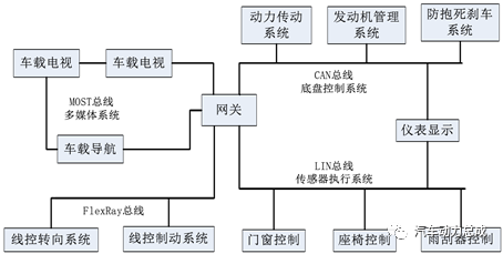
Control units with high real-time requirements, such as linear steering systems and engine control systems, mostly connect using high-speed CAN buses or FlexRay buses. In the automotive body control system, there are many switch devices, including vehicle light control, constant temperature air conditioning systems, and instrument display systems, which do not have high real-time requirements, with communication rates generally between 125 Kbits/s and 1 Mbit/s. These types of control units are numerous in vehicles, and from a cost-performance perspective, low-speed CAN buses can be used to connect these control units. For actuator and sensor components with lower real-time requirements, a single master-multiple slave structure of LIN buses is often used, as low-speed LIN buses can effectively reduce system hardware costs, increase data transmission distances, and improve data interference resistance. For high-end vehicles, entertainment multimedia systems connect using high-speed transmission MOST buses, which can provide data transmission rates of up to 24.8 Mbps; however, due to their lower reliability, they can only be used in less critical parts of the in-vehicle system (such as in-vehicle multimedia systems). Each system is isolated from one another, allowing for parallel operation, and when cross-network communication is needed, data is forwarded through the connected gateways.
For a long time into the future, in-vehicle network systems will continue to connect using a multi-bus coexistence approach. Only through continuous technological development and long-term integration will it be possible to establish a powerful, mature automotive bus protocol standard that can be accepted by all automotive manufacturers.
Note: Data and images cited in the article are sourced from the internet
Your likes and comments are our greatest motivation!
Sponsor Advertisement:
Derivation of the Characteristic Equation of Double Sun Wheel Planetary Gear and Its Application
The Potential and Challenges of Advanced Dynamic Cylinder Stop Technology in Engines
Design and Power Simulation of a Dedicated Hybrid Transmission Scheme
What is Domain Control? How to Empower Automotive Power?
Hybrid Small Classroom – Analysis of Mainstream Dual Motor Hybrid Transmission Technology Solutions (1)
A Comparative Review of Motor Technology for Electric Vehicles
Research on the Application Prospects of Integrated Die Casting Technology
Research on Matching Design of a B-Class Fuel Cell Electric Vehicle
Cornerstone of Intelligent Vehicles – A Comprehensive Review of Steer-by-Wire Technology
A Comprehensive Analysis of Mahle’s Modular Hybrid Power System (MMHP)
Technical Analysis of Audi’s Advanced Composite Turbocharging Mode V8 TDI Engine
Analysis of BorgWarner’s eAWD Torque Vectoring Principle
General Dual-Mode Hybrid System and Its Applications
60000+ An authoritative public account followed by automotive industry technical elites