Introduction
Modbus was developed byMODICONin 1979 and is a standard forindustrial fieldbus protocol. In 1996, Schneider Electric launched the Modbus protocol based on Ethernet TCP/IP: Modbus TCP.
The Modbus protocol is an application layer messaging protocol that includes three types of messages: ASCII, RTU, and TCP.
The standard physical layer interfaces for Modbus protocol include RS232, RS422, RS485, and Ethernet, using a master/slave communication method.
Modbus TCP Data Frame
The Modbus TCP data frame can be divided into two parts: MBAP + PDU.
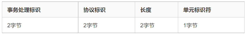
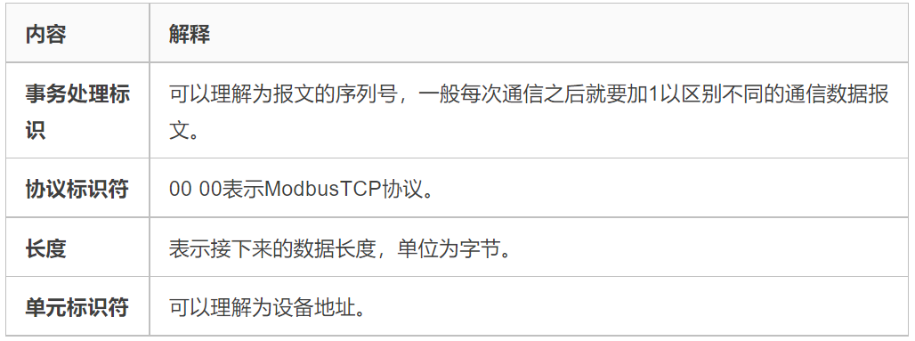
Message Header MBAP
MBAP is the message header, with a length of 7 bytes, composed as follows:
Frame Structure PDU
PDU consists of function code + data. The function code is 1 byte long, and the data length is variable, depending on the specific function.
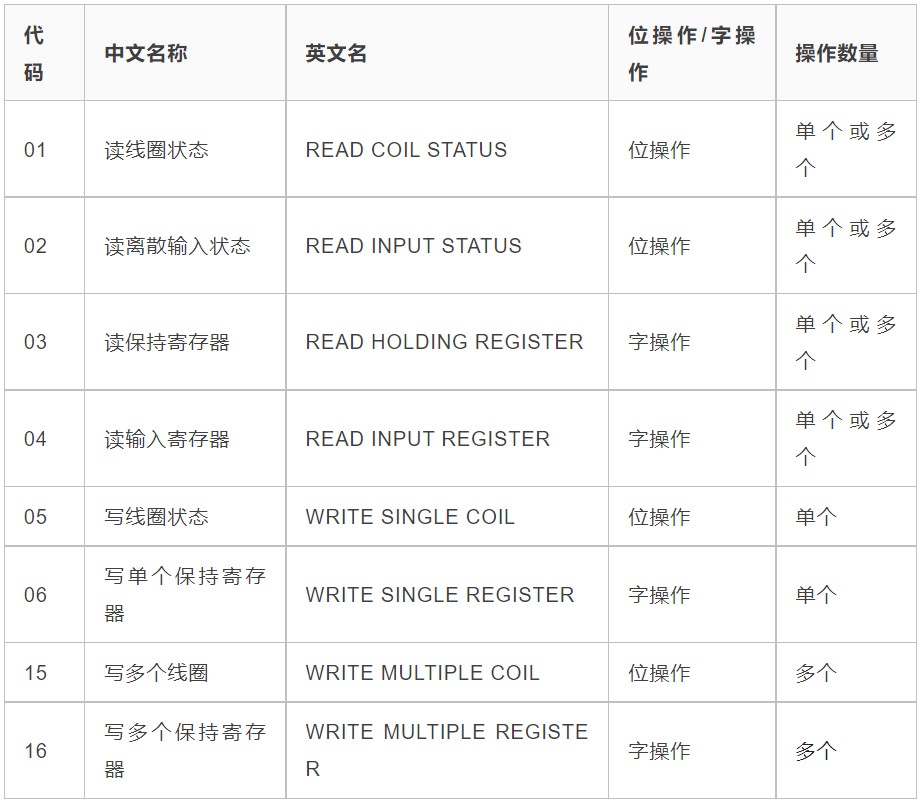
Function Code
There are four types of Modbus operation objects: coils, discrete inputs, holding registers, and input registers.
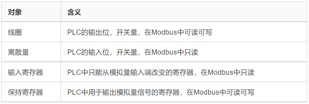
Based on different objects, the Modbus function codes are:
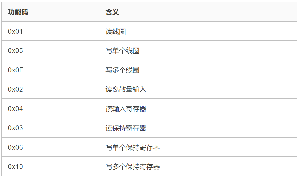
Detailed explanation table:
PDU Detailed Structure
0x01: Read Coils
Read 1 to 2000 continuous coil statuses in the slave, ON=1, OFF=0.
-
Request: MBAP function code starting address H starting address L quantity H quantity L (total 12 bytes)
-
Response: MBAP function code data length data (data for one address is 1 bit)
-
For example: In slave 0x01, read coil data starting from address 0x0002, read 0x0008 bits 00 01 00 00 00 06 01 01 00 02 00 08
-
Response: Data length is 0x01 byte, data is 0x01, the first coil is ON, the rest are OFF 00 01 00 00 00 04 01 01 01 01
0x05: Write Single Coil
Set one output in the slave to ON or OFF, 0xFF00 request output to ON, 0x000 request output to OFF.
-
Request: MBAP function code output address H output address L output value H output value L (total 12 bytes)
-
Response: MBAP function code output address H output address L output value H output value L (total 12 bytes)
-
For example: Set the coil at address 0x0003 to ON 00 01 00 00 00 06 01 05 00 03 FF 00
-
Response: Write successful 00 01 00 00 00 06 01 05 00 03 FF 00
0x0F: Write Multiple Coils
Force each coil in a sequence in a slave to ON or OFF, bits set to 1 in the data field request corresponding output bits to be ON, bits set to 0 request corresponding output bits to be OFF.
-
Request: MBAP function code starting address H starting address L number of outputs H number of outputs L byte length output value H output value L
-
Response: MBAP function code starting address H starting address L number of outputs H number of outputs L
0x02: Read Discrete Inputs
Read 1 to 2000 continuous discrete input statuses from a slave.
-
Request: MBAP function code starting address H starting address L quantity H quantity L (total 12 bytes)
-
Response: MBAP function code data length data (length: 9 + ceil(quantity/8))
-
For example: Read 0x0012 discrete inputs starting from address 0x0000 00 01 00 00 00 06 01 02 00 00 00 12
-
Response: Data length is 0x03 bytes, data is 0x01 04 00, indicating the first discrete input and the 11th discrete input are ON, the rest are OFF 00 01 00 00 00 06 01 02 03 01 04 00
0x04: Read Input Registers
Read 1 to 2000 continuous input registers from a remote device.
-
Request: MBAP function code starting address H starting address L register quantity H register quantity L (total 12 bytes)
-
Response: MBAP function code data length register data (length: 9 + register quantity × 2)
-
For example: Read register data starting from address 0x0002, quantity 0x0005 00 01 00 00 00 06 01 04 00 02 00 05
-
Response: Data length is 0x0A, the first register data is 0x0c, the rest is 0x0000 01 00 00 00 0D 01 04 0A 00 0C 00 00 00 00 00 00 00 00
0x03: Read Holding Registers
Read the contents of a continuous block of holding registers from a remote device.
-
Request: MBAP function code starting address H starting address L register quantity H register quantity L (total 12 bytes)
-
Response: MBAP function code data length register data (length: 9 + register quantity × 2)
-
For example: Starting address is 0x0000, register quantity is 0x0003 00 01 00 00 00 06 01 03 00 00 00 03
-
Response: Data length is 0x06, the first register data is 0x21, the rest is 0x0000 01 00 00 00 09 01 03 06 00 21 00 00 00 00
0x06: Write Single Holding Register
Write a holding register in a remote device.
-
Request: MBAP function code register address H register address L register value H register value L (total 12 bytes)
-
Response: MBAP function code register address H register address L register value H register value L (total 12 bytes)
-
For example: Write data 0x000A to register at address 0x0000 00 01 00 00 00 06 01 06 00 00 00 0A
-
Response: Write successful 00 01 00 00 00 06 01 06 00 00 00 0A
0x10: Write Multiple Holding Registers
Write a continuous block of registers (1 to 123 registers) in a remote device.
-
Request: MBAP function code starting address H starting address L register quantity H register quantity L byte length register value (13 + register quantity × 2)
-
Response: MBAP function code starting address H starting address L register quantity H register quantity L (total 12 bytes)
-
For example: Write data to register starting address 0x0000, quantity 0x0001, data length is 0x02, data is 0x000F 00 01 00 00 00 09 01 10 00 00 00 01 02 00 0F
-
Response: Write successful 00 01 00 00 00 06 01 10 00 00 00 01
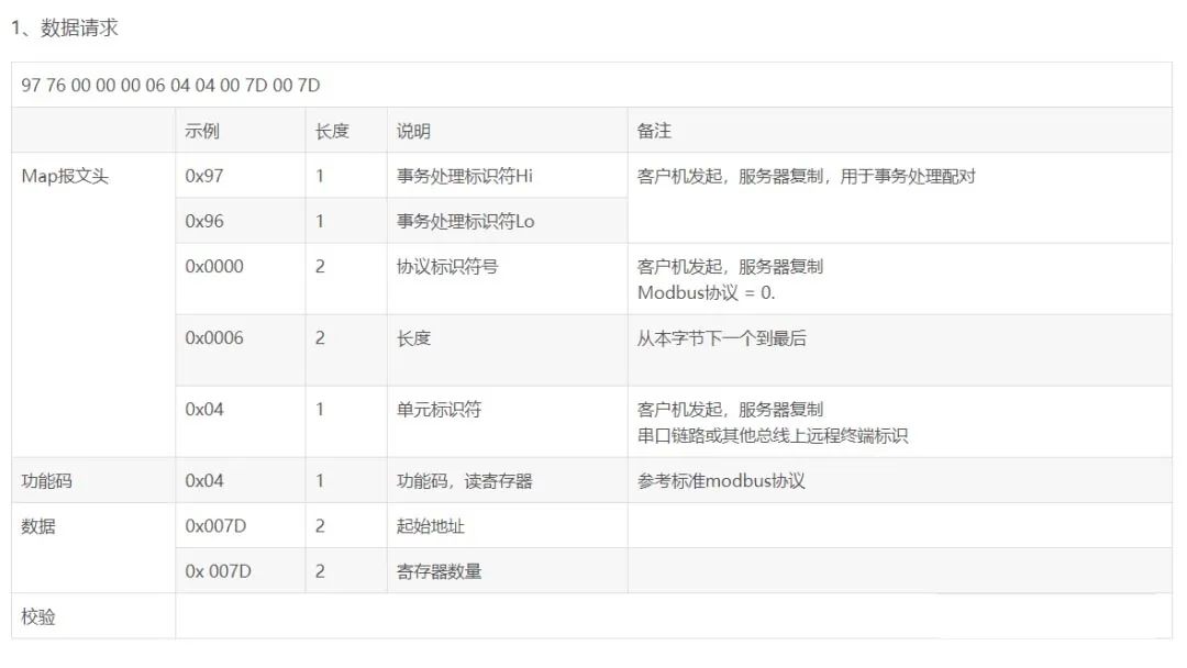
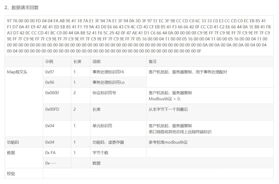
Modbus TCP Example Messages
Modbus TCP and serial Modbus have consistent data fields, and specific data fields can refer to serial Modbus. Here are a few Modbus TCP link analysis explanations to assist newcomers in analyzing messages.
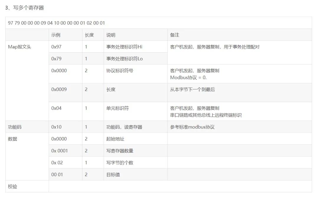
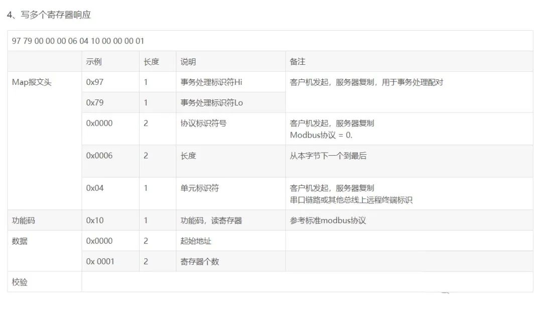
Function code 0x10: Write multiple holding registers, the above two images are incorrect.
Modbus TCP Communication
Communication Method
Modbus devices can be divided into master (poll) and slave. There is only one master, and multiple slaves. The master sends request frames to each slave, and the slave responds. When using TCP communication, the master is the client side, actively establishing a connection; the slave is the server side, waiting for the connection.
-
Master request: function code + data
-
Slave normal response: requested function code + response data
-
Slave abnormal response: abnormal function code + error code, where the abnormal function code is the most significant bit of the requested function code set to 1, and the error code indicates the type of error
-
Note: A timeout management mechanism is needed to avoid indefinite waiting for a potentially non-existent response
IANA (Internet Assigned Numbers Authority) has assigned the TCP port number of 502, which is currently the only assigned port number in the instrumentation and automation industry.
Communication Process
-
connect to establish TCP connection
-
Prepare Modbus message
-
Use send command to send the message
-
Wait for response on the same connection
-
Use recv command to read the message, completing a data exchange
-
Close the TCP connection when the communication task is finished
Simulation Software
-
Modbus Poll and Modbus Slave are a set of Modbus simulation software that can implement Modbus RTU, TCP, serial simulation, etc.
-
Simulation software website: https://modbustools.com/download.html
-
In Modbus TCP, Modbus Poll acts as the client requesting data, while Modbus Slave acts as the server handling requests.
-
When writing a client in C language to connect to Modbus Slave, pay attention to the data format; a command must be sent all at once, otherwise the connection will fail.
-
When using the software, it is necessary to specify the function code, set in setup->slave definition or poll definition. – slave ID: slave number (transaction identifier) – function: function code, 0x01 corresponds to coil operation, 0x02 corresponds to discrete operation, 0x03 corresponds to holding register operation, 0x04 corresponds to input register operation – address: starting address – quantity: number of registers/coils/discrete inputs
Some Concepts
In industrial automation control, various concepts such as switch quantity, digital quantity, analog quantity, discrete quantity, and pulse quantity are often encountered, and people can easily confuse these concepts in practical applications. The various concepts are listed as follows:
1. Switch Quantity
Generally refers to the “on” and “off” states of contacts, which are also represented by “0” or “1” in computer equipment.
Switch quantities are divided into active switch quantity signals and passive switch quantity signals. Active switch quantity signals refer to “on” and “off” states that carry power, professionally called step signals, which can be understood as pulse quantities;
Typical signals include 220VAC, 110VAC, 24VDC, 12VDC, etc., while passive switch quantity signals refer to “on” and “off” states that do not carry power, generally known as dry contacts. The resistance testing method yields a resistance of 0 or infinity.
2. Digital Quantity
Many people confuse digital quantity with switch quantity and analog quantity. Digital quantity is a discrete physical quantity in both time and quantity, represented by digital signals. Digital quantity consists of signals made up of 0 and 1, encoded to form regular signals; the quantized analog quantity becomes the digital quantity.
3. Analog Quantity
The concept of analog quantity corresponds to digital quantity, but can be converted into digital quantity after quantization. Analog quantity is a continuous physical quantity in both time and quantity, represented by analog signals. Any value in the continuous change process of analog quantity is a specific meaningful physical quantity, such as temperature, voltage, current, etc.
4. Discrete Quantity
Discrete quantity is the physical quantity obtained by discretizing the analog quantity. That is, no instrument can completely accurately represent the analog quantity because they all have a sampling period, during which the physical quantity value remains unchanged, while the actual analog quantity varies. This discretizes the analog quantity into discrete quantity.
5. Pulse Quantity
Pulse quantity is the signal quantity when the instantaneous voltage or current jumps from one value to another. After quantization, its change continues regularly, becoming a digital quantity; if it changes from 0 to a fixed value and remains unchanged, it is a switch quantity.
In summary, analog quantity is a physical quantity that changes continuously in time and quantity during a certain process. Due to the sampling period of all instruments for external data collection, the collected data only changes at the start of the next sampling period; its value does not change during the sampling period.
This discretizes the analog quantity. For example, if a device has a sampling period of 1 second, and the temperature collected at the fifth second is 35 degrees, while the sixth second’s temperature is 36 degrees, the device can only indicate 35 degrees at the fifth second and 36 degrees at the sixth second, while the temperature at five and a half seconds is also marked as 35 degrees, even though the actual analog quantity is 35.5 degrees. This discretizes the analog signal. The collected data is thus discretized, no longer a continuous analog signal.
Since computers only recognize two signals, 0 and 1, switch quantity signals are used to represent values using digital strings. Due to computational limitations, the digital strings cannot be infinitely long, meaning their precision is also limited. Taking temperature as an example, due to the limitations of the digital strings, the precision of temperature representation can only reach 0.1 degrees; values smaller than this unit cannot be indicated. Thus, discrete quantities must be quantized into digital quantities. For instance, a temperature of 35.68 degrees would be represented as 35.6 degrees.
Disclaimer:This article is reprinted from the internet, and the copyright belongs to the original author. If there are copyright issues with the work, please contact us in time to delete it, thank you!
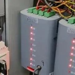
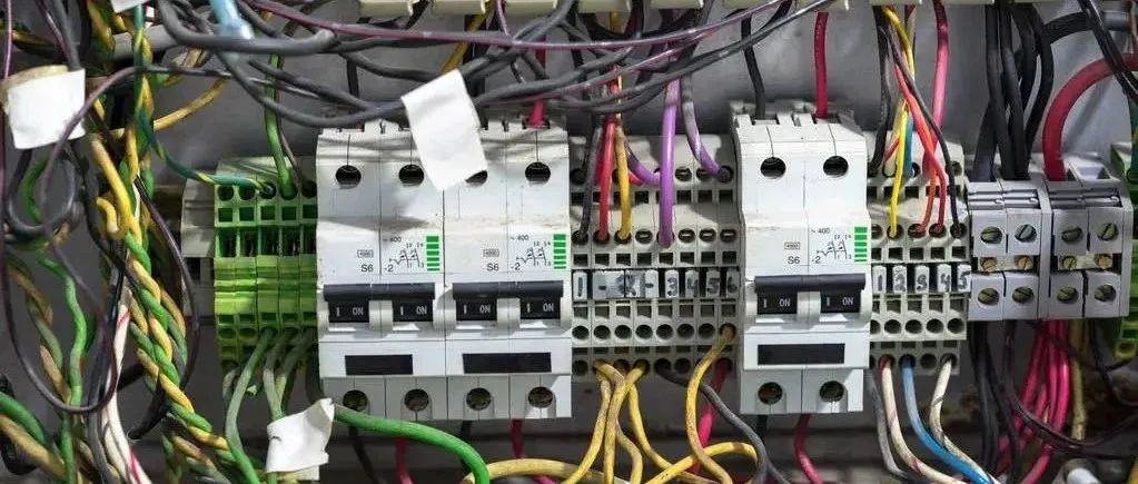
Mysterious devices often appear in distribution cabinets; many electricians probably don’t know what they are.
2024-04-21
If you understand these 33 points in the classic multimeter mnemonic, you will master the multimeter.
2024-04-21

Is communication between S7-1200 and SMART S7 difficult? Here comes a super detailed tutorial that teaches you step by step!
2024-04-20
Polling communication applications between Mitsubishi FX3U and multiple Mitsubishi inverters.
2024-04-20

Why does a 60A air switch trip with only 30-something A of current?
2024-04-19
Scan the QR code below↓↓↓
Free access to the complete Siemens set
 Click to read the original text,download the complete Siemens set