The RS232 type DB9 interface, which used to be found on older computers, can be connected to modems. In MCU51 microcontroller projects, this UART interface is generally used, with serial port rates of 115200bps, 57600bps, etc. Later, USB to serial converters like PL2302 and FT232 emerged, with rates reaching up to 921600bps, which is considered the highest. Since various microcontrollers are equipped with UART interfaces, whether MCU51 or ARM, this is the most familiar interface for everyone.
RS232 interface was established in 1970 by the Electronic Industries Association (EIA) in collaboration with Bell System, modem manufacturers, and computer terminal manufacturers as a standard for serial communication. Its full name is “Serial Binary Data Exchange Interface Standard between Data Terminal Equipment (DTE) and Data Communication Equipment (DCE)”. This standard specifies the use of a 25-pin DB25 connector and outlines the signal content for each pin as well as the voltage levels for various signals.
Generally, only three pins of the DB25 serial port are used: 2 (RXD), 3 (TXD), and 7 (GND). With continuous improvements in devices, the DB25 connector is rarely seen now, replaced by the DB9 interface, which uses a different pin configuration: 2 (RXD), 3 (TXD), and 5 (GND). Therefore, the RS232 interface is now commonly referred to as DB9.

In the market, the male connector is called DRXX, and the female connector is called DBXX. For example, the serial port on our computer is referred to as DR9 in the market, not DB9. Many people mistakenly call it DB9, while the actual DB9 is an interface that connects two DR9 connectors together. In textbooks or articles, all serial device interfaces are often uniformly referred to as RS232 interfaces.
Since the RS232 interface standard was introduced early on, it inevitably has some shortcomings, mainly four points:
(1) The signal voltage levels of the interface are relatively high, which can damage the circuit chips, and since it is not compatible with TTL levels, a level conversion circuit is necessary to connect to TTL circuits.
(2) The transmission rate is relatively low, with a baud rate of 20Kbps during asynchronous transmission.
(3) The interface uses one signal line and one signal return line, forming a common ground transmission format, which is prone to common-mode interference, resulting in weak noise immunity.
(4) The transmission distance is limited, with a maximum standard transmission distance of 50 feet, and practically can only be used for about 50 meters.
To address the shortcomings of the RS232 interface, new interface standards have continuously emerged, with RS-485 being one of them, featuring the following characteristics:
(1) The electrical characteristics of RS-485: Logic “1” is represented by a voltage difference of +(2-6)V between the two lines; Logic “0” is represented by a voltage difference of -(2-6)V between the two lines. The signal voltage levels of the interface are lower than those of RS-232, making it less likely to damage the circuit chips, and this level is compatible with TTL levels, facilitating connection with TTL circuits.
(2) RS-485 has a maximum data transmission rate of 10Mbps.
(3) The RS-485 interface uses a combination of balanced drivers and differential receivers, enhancing common-mode rejection capability, thus improving noise immunity.
(4) The maximum standard transmission distance for RS-485 is 4000 feet, practically reaching 3000 meters. Additionally, the RS-232 interface allows only one transceiver on the bus, indicating single-station capability, while RS-485 allows up to 128 transceivers on the bus, indicating multi-station capability, allowing users to easily establish a device network using a single RS-485 interface.
Because the RS485 interface forms a half-duplex network, it generally requires only two wires (commonly referred to as A and B lines), so RS485 interfaces use shielded twisted pair cables for transmission.
Since some devices use RS232 interfaces while others use RS485 interfaces, if an RS232 device needs to communicate with an RS485 device, an RS232/RS485 converter is required to convert the RS232 signals to RS485 signals before communication can occur. If two RS232 devices need to communicate over a long distance, only two RS232/RS485 conversion circuits need to be added.
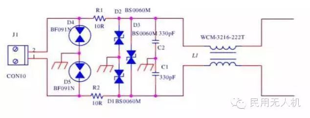
The so-called “passive RS232/RS485 converters” in the market utilize power-stealing technology from computer serial ports, while “active RS232/RS485 converters” have similar circuit diagrams to the former, differing only in the power supply section.
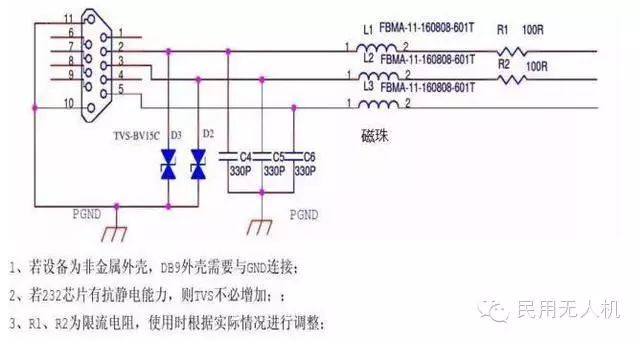
RS485 interface EMC design reference
Differences between RS485 and RS232 protocols:
1. The electrical characteristics of RS-485: Logic “1” is represented by a voltage difference of +(2-6)V between the two lines; Logic “0” is represented by a voltage difference of -(2-6)V between the two lines. The interface signal levels are lower than RS-232-C, making it less likely to damage the circuit chips, and this level is compatible with TTL levels, facilitating connection with TTL circuits.
2. RS-485 has a maximum data transmission rate of 10Mbps.
3. The RS-485 interface uses a combination of balanced drivers and differential receivers, enhancing common-mode rejection capability, thus improving noise immunity.
4. The maximum standard transmission distance for RS-485 is 4000 feet, practically reaching 3000 meters. Additionally, the RS-232-C interface allows only one transceiver on the bus, indicating single-station capability, while the RS-485 interface allows up to 128 transceivers on the bus, indicating multi-station capability. The advantages of RS-485, such as good noise immunity, long transmission distances, and multi-station capability, make it the preferred serial interface. As the RS-485 interface forms a half-duplex network, it generally requires only two wires, so RS-485 interfaces use shielded twisted pair cables for transmission.
The RS485 interface connector uses a DB-9 9-pin plug and socket, with the smart terminal RS485 interface using DB-9 (female), and the keyboard connection interface using DB-9 (male).
Sync serial interfaces include SPI, IIC, etc., with SPI being relatively faster, reaching several M or even tens of M. UART and similar interfaces belong to asynchronous serial ports, as they need to consider data synchronization signal recovery, so the speed is not high.
Everyone knows about IDE hard disk interfaces, printer interfaces, as well as parallel ports for microcontrollers, ARM, etc., which are significantly faster than serial ports but have many more wires. This can be simply understood as a parallel connection of multiple serial ports. In other words, a parallel port is just multiple serial ports transmitting data simultaneously.
However, one may notice a phenomenon where there are two types of parallel ports. For example, when connecting SDRAM, the difference is quite obvious. SDRAM is much faster than a regular parallel port, easily reaching 100MHz, while a regular parallel port only achieves speeds in the tens of M. Especially for those who have worked with regular mobile phones, they know that the flash interface speed is limited. This is primarily not due to interface speed but due to the bus architecture differences. The earliest Intel 80 interface reads signals as Data, Addr, nCS, nRD, nWR, which requires sending out the address each time. After the chip decodes the selection, it can retrieve the data, resulting in slower speeds. Most MCU51s use this type of bus, known as Intel 80. Additionally, many black-and-white LCD screens use a 68K interface, replacing nRD and nWR with R/W and E. New interfaces generally use Data, Addr, CLK, RAS, CAS, WE, etc., commonly referred to as burst mode parallel ports, while Intel 80 and 68K types are generally called normal mode parallel ports. The biggest advantage of burst mode is that once configured, the address is sent only once, and subsequent data is read continuously through CLK without needing to send the address again or decode the selection process, allowing for pipelined operations, thus significantly increasing speed. This is particularly relevant for CPUs with high-speed RAM or for applications requiring full-screen read/write, such as larger color LCD screens ranging from 3.5 inches to 10 inches, which use this type of interface. On LCD screens, some refer to this as the RGB interface. The ARM9 processor commonly uses this, with R, G, B each having 8 data lines, often not using all of them, dropping some low-order data to form the 565 format, then accompanied by CLK, VS (frame sync signal), HS (line sync signal), and IIC configuration signals.
The common point discussed above is that the transmission of information is based on electrical signals, generally judged by whether the voltage is above or below a certain level to determine 1 or 0. The carrier of electrical signals is the electric field and voltage, so the discussions above are based on conventional circuit loops. The conventional circuit is an approximation of electromagnetic field theory at low speeds, and the propagation of electromagnetic fields leads to multiple reflections and steady states. When the signal frequency increases, this reflection can reduce the clarity of the signal, which is what is referred to as signal integrity degradation, where square waves turn into sine waves and become unrecognizable. Therefore, to further increase communication speed, it is necessary to change the transmission medium from electric fields to electromagnetic fields, thus using specialized transmission lines like microstrip lines and coaxial cables, which have requirements for uniform impedance throughout the transmission line.
Some friends may think of differential signals when they hear about high-speed transmission, but they only understand the external noise immunity. It does not address the signal energy transmission’s own deformation. Only when differential signals are further constrained to meet electromagnetic field impedance requirements can the signal deformation problem be further resolved. Thus, merely understanding differential signals is only partially correct. Furthermore, high-reliability signal transmission often uses coaxial cables and microstrip lines, where the concept of differential does not apply.
Based on this theory, current high-speed serial interfaces have emerged, such as USB, 1394, Ethernet, SATA, LVDS, etc., which have all developed based on electromagnetic field theory. They share a common feature of requiring impedance matching, which is the most fundamental aspect of electromagnetic field theory.
Because technologies based on electromagnetic fields as carriers have speeds far exceeding those based on electric field theory, this represents a leap of one or two orders of magnitude. Thus, it is not surprising that current high-speed serial ports are faster than ordinary low-speed parallel ports.
So one might ask, to further increase the speed, is the current high-speed serial port being parallelized? This is one aspect, such as DDR2, which has already done so. However, there is another trend, such as SATA1X, 2X, 4X, which is not simply parallelization but should be considered networking. In other words, from 1X, 2X to 4X, it has transformed from one channel to four network channels. The data communication method has become similar to the current internet, achieving networking. This is because these interfaces may have a poor connection, and if one channel fails, it does not affect data communication; it only slows down the speed. If it were still a conventional parallel approach, it would completely fail.
Principles and Control of Servos
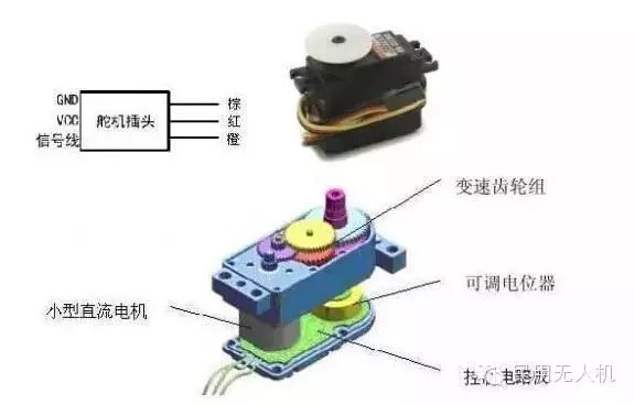
The control signal enters the signal modulation chip from the receiver’s channel, obtaining a DC bias voltage. It has an internal reference circuit that generates a reference signal with a period of 20ms and a width of 1.5ms, comparing the obtained DC bias voltage with the potentiometer voltage to get the output voltage difference. Finally, the positive and negative outputs of the voltage difference are sent to the motor driver chip to determine the motor’s forward or reverse rotation. When the motor speed is constant, the potentiometer rotates through a series of reduction gears, causing the voltage difference to be zero, stopping the motor.
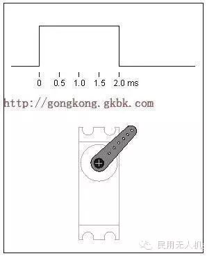
Servo control generally requires a timing pulse of about 20ms, with the high-level portion of the pulse generally within the range of 0.5ms to 2.5ms for angle control pulses, with a total interval of 2ms. For a servo with a 180-degree angle, the corresponding control relationship is as follows:
0.5ms————–0 degrees;
1.0ms————45 degrees;
1.5ms————90 degrees;
2.0ms———–135 degrees;
2.5ms———–180 degrees;
(1) Servo Follow Characteristics
Assuming the servo is stable at point A, and the CPU sends a PWM signal, the servo will move at full speed from point A to point B, which requires a certain amount of time for the servo to reach point B.
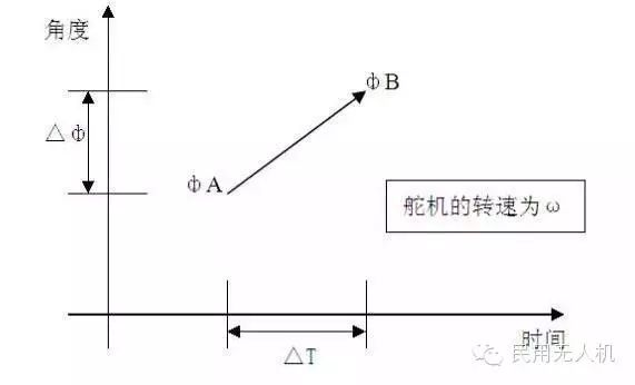
The holding time is Tw
When Tw ≥ ΔT, the servo can reach the target and has remaining time;
When Tw ≤ ΔT, the servo cannot reach the target;
In theory: when Tw = ΔT, the system is most coherent, and the servo moves the fastest.
In practice, the values of w may vary, and calculating the limit ΔT for coherent motion can be quite difficult.
If our servo has 1DIV = 8us, when the PWM signal changes with the minimum increment (1DIV = 8us), the servo’s resolution is the highest, but the speed will slow down.
This article is sourced from: Drone Network
This article is authored by: Feishou Community
Daily updates on drone news and resources!
Long press the QR code to follow us!