Modbus is considered a classic communication protocol in the embedded field. Whether you are a beginner or an engineer with years of experience, it is essential to understand it.
1. What is Modbus?
As the name suggests, it is a bus protocol. For example, serial protocols, IIC protocols, and SPI are all communication protocols. If you are encountering such protocols, it is likely that you are in the industrial electronics field or your products are used in industry.
Now you roughly know that this is a bus protocol, a communication protocol published by a company called Modbus. So why use it? The answer is that everyone is using it, so you need to learn it, haha!
To be serious, it is accepted in the industrial field for three reasons:
-
Publicly published with no copyright requirements -
Easy to deploy and maintain -
Suppliers have few restrictions on modifying local bits or bytes
In summary, it is free + simple + easy to modify!
In conclusion: Modbus is a simple protocol used in industry!
2. What is Modbus used for?
In two words: Communication
Yes, all protocols are used for communication. The purpose of a protocol is to allow two parties to understand a set of transmitted data according to the protocol. For example, if I give you a 6666, without a protocol you would only know it is 6666, but with a protocol, you would know it is asking if I am the boss? Of course, it can mean other things; the specific meaning depends on how the protocol is defined!


In summary: Modbus is used for communication, which everyone knows!
3. What are the contents of Modbus?
It is generally divided into the following types:
-
Modbus-RTU -
Modbus-ASCII -
Modbus-TCP
Among these three protocols, a device will only have one protocol. If your device uses Modbus-RTU, just refer to the corresponding section below; generally, most devices use the Modbus-RTU protocol.
4. Communication Process
Modbus uses master-slave communication, meaning that communication cannot occur simultaneously. Only one data transmission occurs on the bus at a time: the master sends, the slave responds; if the master does not send, there is no data communication on the bus. (So this is also considered a disadvantage)
Example 1: There is one master and multiple slaves on a bus. The master queries one of the slaves. First, you must assign addresses to these slaves (so you know which slave it is, and each address must be unique). After assigning addresses, the master queries, and then sends data (the data content will be introduced below). The slave receives the data sent by the master and then replies from the corresponding address. The master receives the slave’s data; this is a communication process from master to slave. Isn’t it simple? 
Example 2: It’s like making a phone call; you must know the other party’s number (this is the unique address), then you call, which is equivalent to the master querying the slave, and when the other party answers, they reply to you (return data). Normally, this is how it works.
If at this time the other party is on another call, you should hear something like “sorry, you…” indicating that the other party is busy. However, the Modbus bus cannot determine whether the other party is busy and has no corresponding arbitration mechanism. Now you know another disadvantage! However, you can use software methods to appropriately process data!
5 Modbus-RTU Protocol
Devices must have the RTU protocol! This is stipulated by the Modbus protocol, and the default mode must be RTU, with ASCII as an option. (In other words, general devices only have the RTU protocol, and ASCII is rarely used.) Therefore, when learning the Modbus protocol, it is generally sufficient to understand the RTU protocol, while ASCII can be understood as a supplementary learning.
1. Frame Structure
Frame Structure = Address + Function Code + Data + Checksum
-
Address: Occupies one byte, range 0-255, with a valid range of 1-247. Others have special purposes; for example, 255 is the broadcast address (the broadcast address means responding to all addresses; normally, two devices must have the same address to query and reply).
-
Function Code: Occupies one byte. The function code indicates what the instruction is for; for example, you can query data from the slave or modify data, so different function codes correspond to different functions.
-
Data: Varies depending on the function code, with different structures explained in the examples below.
-
Checksum: Added to ensure data integrity; it calculates the previous data to check if it is consistent. If consistent, it means this frame of data is correct, and I will reply; if not, it means there was a problem during transmission, and the data is incorrect, so it is discarded.
2. Practical Example
Discussing theory alone may not be clear; below is an example. The function codes we most frequently use with the Modbus-RTU protocol are 03 and 06. Most of the time, we use Modbus to query information from sensors using 03 for the query function code; if we need to modify the sensor register value, we use 06 for modification. You don’t need to focus on other codes too much; you won’t remember them all anyway, haha!
2.1 Query Function Code 0x03
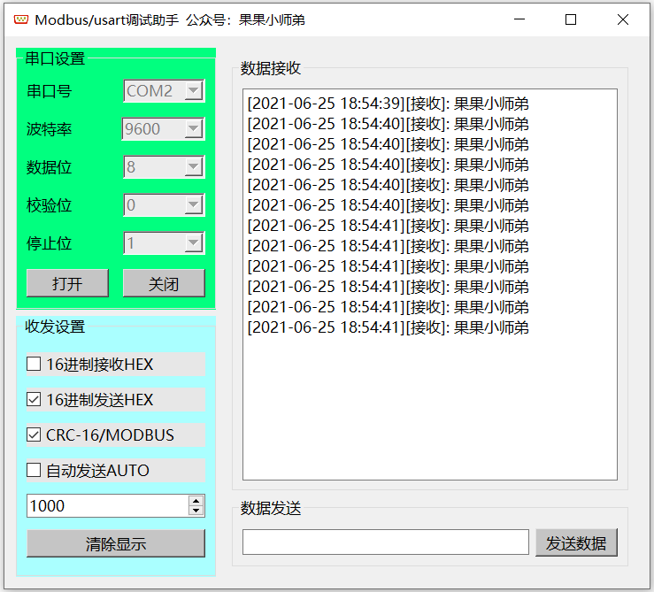
Function Description: Now I am the master, and I want to query the data from the slave with address 01. I will use the Modbus debugging assistant on the computer to replace the master and STM32 to replace the slave.
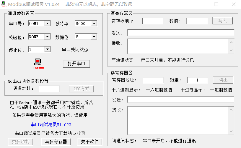
I need to send the following data:
Master sends: 01 03 00 00 00 01 84 0A
Slave replies: 01 03 02 19 98 B2 7E
What does this set of data mean?
From the structure above, we can see that the data sent by the master is roughly Address + Function Code + Data + Checksum;
So the parsing is as follows:
Sent Data Parsing
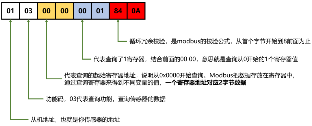
01 - Address, which is the address of your sensor
03 - Function code, 03 represents the query function, querying the sensor's data
00 00 - Represents the starting register address for the query, indicating starting from 0x0000.
Here it should be noted that Modbus stores data in registers, and the values of different variables can be obtained by querying registers. One register address corresponds to 2 bytes of data.
00 01 - Represents querying one register. Combined with the previous 00 00, it means querying the value of one register starting from 0.
84 0A - Cyclic Redundancy Check, which is the Modbus check formula, from the first byte up to before 84;
Reply Data Parsing
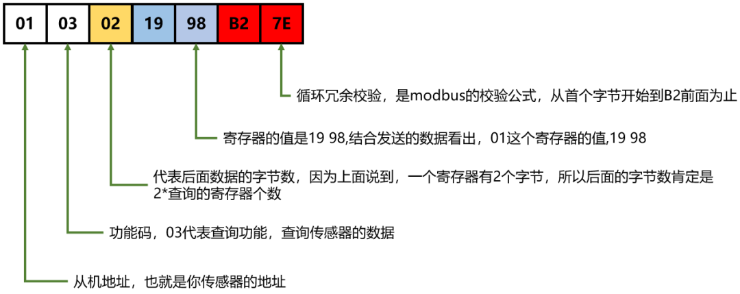
01 - Address, which is the address of your sensor
03 - Function code, 03 represents the query function, querying the sensor's data. Here it should be noted that the function code sent to the slave must be the same as the one sent by the master; if different, it indicates that this frame of data is erroneous.
02 - Represents the byte count of the following data; since it was mentioned earlier that one register has 2 bytes, the byte count must be 2 times the number of queried registers;
19 98 - The value of the register is 19 98, combined with the sent data, it shows that the value of register 01 is 19 98.
B2 7E - Cyclic Redundancy Check;
Alright, isn’t it simple? The basic process is:
-
Send: Slave’s address + Function code indicating what I want to do + Address of the register I want to query + Number of registers to query + Checksum;
-
Reply: Slave’s address + Function code sent by the master + Number of bytes of data to be sent to the master + Data + Checksum;
It’s that simple!
2.2 Modification Function Code 0x06
If I want to modify data from the slave, is there a protocol for that? Of course, there is, and it is 0x06.
1. Modification – 0x06 Function Code
Master sends: 01 06 00 00 00 01 48 0A
Slave replies: 01 06 00 00 00 01 48 0A
Hey, why do they look the same? Is it wrong? The answer is that this is correct;
Sent Data Parsing
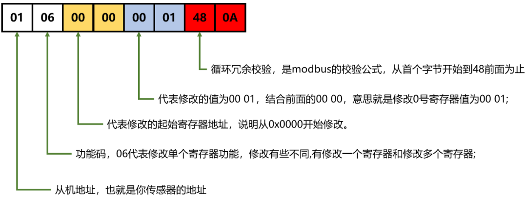
01 - Address of the slave the master wants to query
06 - Function code, 06 represents the function of modifying a single register; modification has some differences, such as modifying one register or multiple registers;
00 00 - Represents the starting register address for modification, indicating starting from 0x0000.
00 01 - Represents the value to be modified as 00 01. Combined with the previous 00 00, it means modifying the value of register 0 to 00 01;
48 0A - Cyclic Redundancy Check, which is the Modbus check formula, from the first byte up to before 48;
Reply Data Parsing

01 - The slave returns its address to the master, indicating that this is the slave being queried by the master
06 - Function code, representing the function of modifying a single register; the slave must reply with the same function code sent by the master;
00 00 - Represents the starting register address for modification, indicating it is 0x0000.
00 01 - Represents the value to be modified as 00 01. Combined with the previous 00 00, it means modifying the value of register 0 to 00 01;
48 0A - Cyclic Redundancy Check, which is the Modbus check formula, from the first byte up to before 48;
If the reply is the same, it indicates that the modification was successful; if the function code is 06 but something else, it indicates that the slave’s reply data is erroneous, and the master can take appropriate actions.
2. Modification – 0x10 Function Code
If I want to modify multiple registers, would it be silly to use 06 multiple times? Therefore, the Modbus RTU protocol includes a method for modifying multiple continuous registers, which is function code 0x10; you can look it up yourself, and the data format is basically similar to the above.
Conclusion
For the Modbus-RTU protocol, you only need to understand the function codes 0x03, 0x06, and 0x10 to be sufficient. Recall their data domain parts:
0x03—The master needs to send the starting address + number of registers, and the slave replies with total bytes + data;
0x06—The master sends starting address + data content (since you only need to modify one, the starting address is the address to be modified), and the slave returns starting address + data content (surprisingly, they are the same!).
0x10—The master sends starting address + number of registers + total bytes + data, and the slave returns starting address + number of registers;
6 Modbus-ASCII Protocol
Generally, you only need to understand the RTU protocol because it has been mentioned that the RTU protocol is mandatory. Once you understand the RTU protocol, you can read device information; as for the ASCII protocol, just have a general understanding.
1. Frame Format
For the RTU protocol, for example, sending one byte: 0x12; the ASCII protocol requires sending 2 bytes: one byte represents ASCII code 1, and one represents ASCII code 2, i.e., 0x31 and 0x32, to represent 0x12. Therefore, the efficiency of the ASCII protocol is relatively low. However, ASCII is more suitable for serial port printing and viewing since the data sent over the serial port is generally in text mode (ASCII).
For instance, using the RTU method, also called hexadecimal method, to send 0x03 data, the RTU method sends 00000011. Using ASCII to send 0x03, it sends the ASCII code for 0 0x30 and the ASCII code for 3 0x33, corresponding to binary, which would send 00110000 and 00110011. Clearly, the RTU method only needs to send 8 bits (plus start and stop bits, totaling 10 bits of data). The ASCII code method, however, needs to send two 8 bits (each 8 bits, plus start and stop bits, totals 20 bits of data). This means that the data sent in ASCII mode is twice that of the RTU method, making ASCII less efficient.
So why use the ASCII code sending method, which is less efficient and has a larger data volume?
Because if you want to send data 0x03, using the RTU method (hexadecimal sending), the computer’s terminal device cannot display 0x03, meaning it cannot print it out. The visible character ASCII codes range from 32-126; anything outside this range will not display on screens, leading to garbled text. If it’s a serial port assistant, it will display □□□□. If you use the ASCII method (text mode sending), this will not lead to undetectable or garbled situations because sending 0x03 in text mode means sending ASCII codes 0 and 3, which are 0x30 and 0x33, and can be displayed correctly on the computer terminal. Now you understand why the less efficient ASCII method is still used, right? It’s just for debugging display convenience.
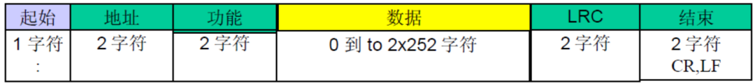
From the above figure, we can see:
1) The RTU has additional start segments : and multiple end symbols CR, LF;
2) The address and function have become 2 bytes;
3) The data section is more complicated but more suitable for human viewing;
2. Summary
Since both Modbus-RTU and Modbus-ASCII are based on 232 and 485 links, their communication mode is half-duplex, typically in a master-slave mode. The difference lies in their byte formats: one uses hexadecimal data, and the other uses ASCII data. ASCII has additional frame heads and tails, allowing the use of these heads and tails to determine when a frame of bytes ends; whereas RTU lacks frame heads and tails, so the protocol clearly states that the time interval between two frames must exceed 3.5 bytes to serve as a basis for judging the end of a frame. For RS485, the bus generally allows a maximum of 32 devices.
7 Notes
Finally, a few additional points: The response data format from Modbus slaves is: 1. The response data packet format is consistent with the master query data packet format. When the slave responds normally: the function code is consistent with the function code sent by the master (1-127). In case of an abnormal response: the function code must be added 128 to the master’s function code. Don’t ask why 128; ask the people who created the protocol!
Since computers only support USB, we need to convert USB to TTL serial, then convert it to the 485 interface to connect with the microcontroller; this is the most basic hardware, but it also requires attention.
Finally, I modified the serial debugging assistant to add a CRC check function, and it can be obtained.

Click “Read the original text” to see more shares.