Design of Bus Short-Circuit Isolators

Click AboveElectricalI
1 Analysis of Bus Short-Circuit Isolator Settings
1.1 Significance of Bus Short-Circuit Isolator Settings
When a short circuit occurs in the fire alarm system’s bus circuit, the fault circuit will pull down the voltage of the entire fire alarm system, leading to system paralysis and failure. To prevent this situation, the “Specification” requires the installation of short-circuit isolators in the system bus circuit, which can quickly isolate the fault circuit under short-circuit conditions, maximizing the protection of the overall system functionality from the impact of the fault circuit.
The regulation that the total number of devices should not exceed 32 points comes from product standard GB 4717 – 2005 “Fire Alarm Controller” Clause 5.2.4.10: “When the controller operates in bus mode, it should have a bus short-circuit isolator. When the short-circuit isolator operates, the controller should be able to indicate the location number of the isolated component.”
When a short circuit occurs in a bus that triggers the short-circuit isolator, the number of components affected by the isolator should not exceed 32. The reason for setting the limit at 32 points, in the author’s opinion, is first to consider that if the number of devices protected by the bus short-circuit isolator is too few, although it can increase system reliability, it increases the number of isolators, thus raising the overall project cost; secondly, if the number of devices protected is too many, it will inevitably enlarge the fault range, reducing the protection scope of the fire alarm system.
1.2 Meaning of the 32 Points in the Regulation
Since the regulation limits the total number of fire protection devices protected by each bus short-circuit isolator, how to calculate the total number of fire protection devices becomes crucial. The “Illustration of Fire Alarm System Design Specification” (hereinafter referred to as “Illustration”) provides calculation principles on page 11.
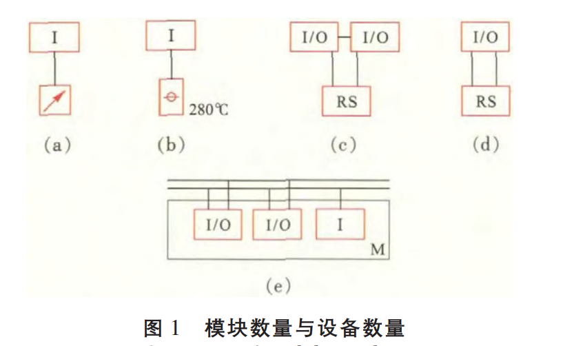
The 32 points mentioned in the regulation refer to the number of fire protection devices, not the number of addresses. Standard tested modules (such as input/output modules or multi-input/output modules) are counted as one device.
For example: an input module with a water flow indicator counts as 1 device; an input/output module with a motorized fire damper counts as 1 device; two input/output modules connected to a two-step lowering fire curtain control box count as 2 devices; if a dual input/output module is connected to a two-step lowering fire curtain control box, it counts as 1 device (Note: Fire protection devices include modules). See Figure 1 (a) ~ (d) for all symbol meanings in this article (refer to “Illustration” page 5). For module boxes (non-standard tested products), the number of devices should be calculated based on the actual fire protection devices connected to the modules within the box (as shown in Figure 1 (e), where the number of devices is 3).
Design of Bus Short-Circuit Isolators
1.3 Wiring of Bus Short-Circuit Isolators
The “Specification” Clause 3.1.6 mentions that the bus refers to the alarm bus and power bus. The bus short-circuit isolator should have the function of isolating faults on the alarm bus and power bus. This part has been explained in “Illustration” page 11, hint 2.
However, currently mainstream products only have short-circuit isolation functions for the alarm bus, and only a few manufacturers’ products have short-circuit isolation functions for the power bus. With the publication of the “Specification” and “Illustration”, the Shenyang Fire Research Institute of the Ministry of Public Security will coordinate the modification of corresponding product standards, and new products will soon emerge.
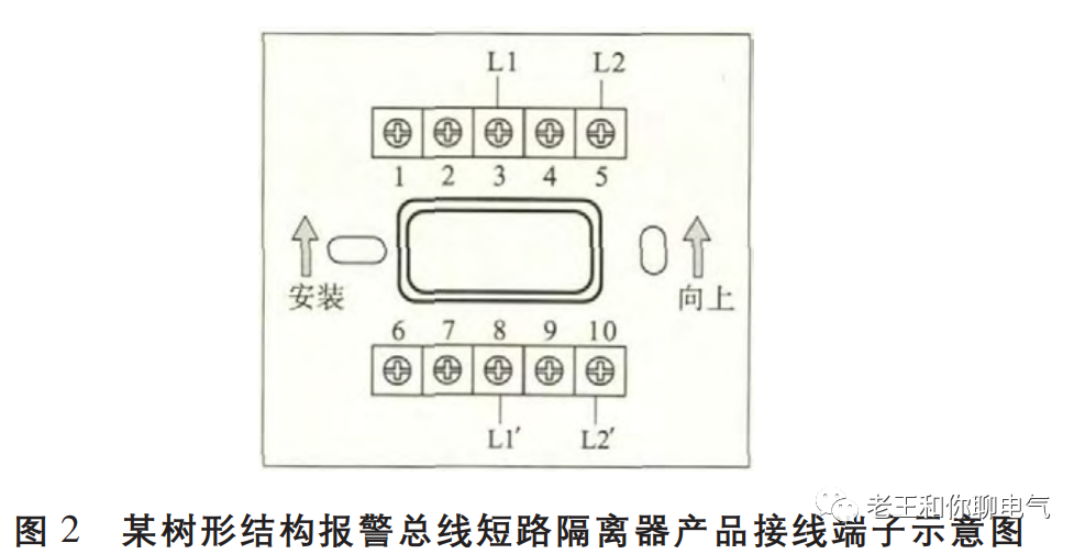
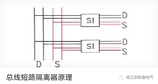
Below are two diagrams illustrating the wiring forms of current tree-structured alarm bus short-circuit isolator products. Figure 2 is a schematic diagram of the terminal connections of a certain alarm bus short-circuit isolator product, where the input terminals are 3 and 5, and the output terminals are 8 and 10. Figure 3 is its wiring schematic, where each tree-structured alarm bus short-circuit isolator is connected in parallel to the alarm bus. When a short circuit occurs in the circuit connected to a specific alarm bus short-circuit isolator, the isolator automatically isolates the faulty circuit, while other circuits remain unaffected.
Currently, fire alarm system products designed with a ring structure have some fire detectors that inherently have isolation functions. In such cases, there is no need to separately install an alarm bus short-circuit isolator. However, domestic products mainly adopt tree-structured systems, and designers should determine the system form based on the nature of the project and the client’s requirements.
Design of Bus Short-Circuit Isolators
1.4 Settings of Bus Short-Circuit Isolators When Crossing Fire Partition
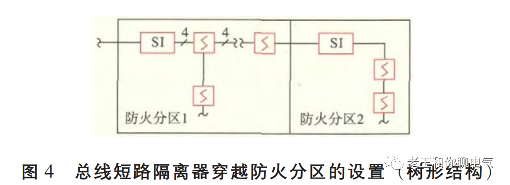
The settings of bus short-circuit isolators when crossing fire partitions are explained in the “Illustration”. Here, it is emphasized again that in a tree-structured system, the bus short-circuit isolator should be installed within the fire partition it protects, as shown in Figure 4 (this diagram uses the alarm bus as an example), with the wiring method shown in Figure 3. In a ring-structured system, the bus short-circuit isolator can be installed in any side of the fire partition, refer to “Illustration” 3.1.6 Figure 3.
Design of Bus Short-Circuit Isolators
2 Project Example
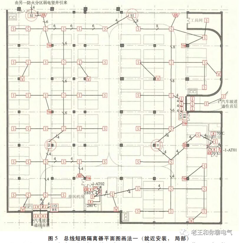
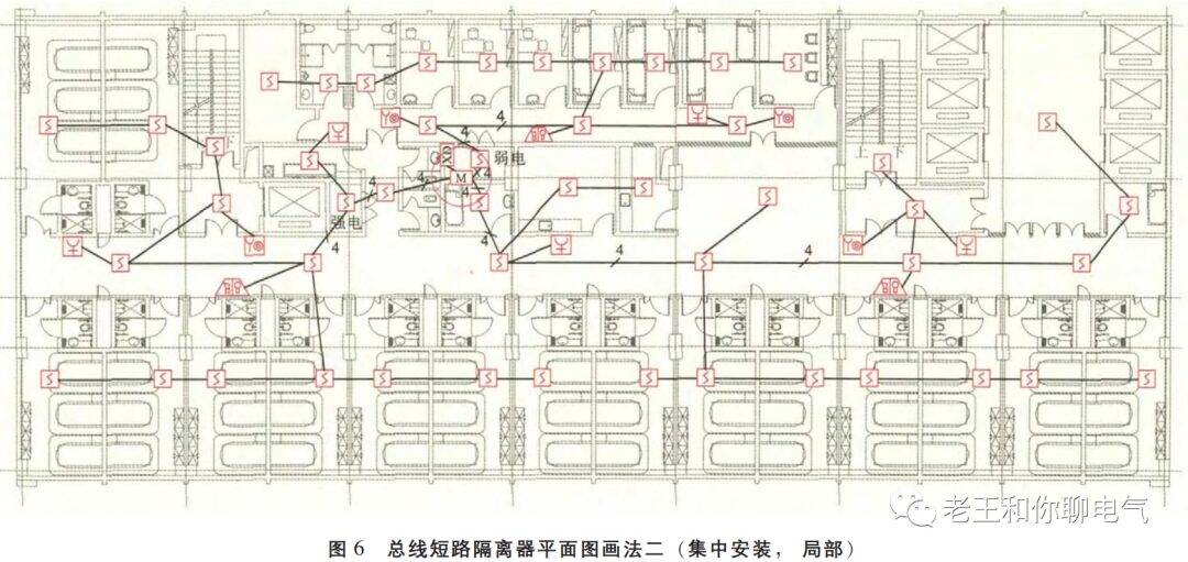
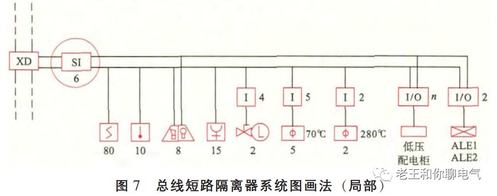
In the “Illustration”, in order to clearly express the wiring method of the bus short-circuit isolator, the system diagram is relatively complicated. To alleviate the burden on designers, the author believes that in actual projects, the drawing method can be slightly simplified. As mentioned in hint 3 on page 12 of the “Illustration”, bus short-circuit isolators can be placed in module boxes or installed close to the route on the wall. Specific methods can refer to Figures 5 and 6. Figure 5 shows the method of installing the bus short-circuit isolator close to the route on the wall, and Figure 6 shows the bus short-circuit isolators concentrated in the weak current vertical shaft module box, while Figure 7 shows the system diagram method.
Design of Bus Short-Circuit Isolators

Design of Bus Short-Circuit Isolators

Design of Bus Short-Circuit Isolators
The floor plan should clearly indicate the specific installation locations of the bus short-circuit isolators (see Figures 5 and 6 with red circles), and the number of wires should be clearly marked. The floor plan should be designed to show that the bus short-circuit isolators simultaneously isolate the power bus and signal bus, indicating only the power and signal buses without reflecting other lines.
In the system diagram, the total number of bus short-circuit isolators can be uniformly marked (see the red circles in Figure 7), and the specific laying method can be seen in the floor plan (Note: Figures 5, 6, and 7 have no corresponding relationship). It is worth reminding that if the system drawing adopts this drawing method, then the floor plan must be designed according to the specification requirements to place the bus short-circuit isolators to avoid issues such as failing to pass the drawing review or missing pipe laying during construction.

This article is fully published in the “Building Electrical” 2015 Issue 9; please refer to the magazine for the full text.

Copyright belongs to “Building Electrical”.
Further Reading

Design of Bus Short-Circuit Isolators

Design of Bus Short-Circuit Isolators

Leave a Comment