After downloading the prepared program to the PLC, it begins to scan the user program, which is its core function. The entire scanning process is referred to as a scan cycle, as shown in the figure below.
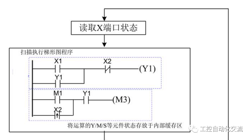
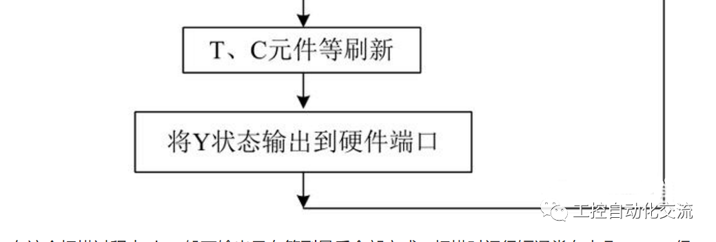
First, it detects the input signal X, then scans the program, such as the ladder diagram, and temporarily stores the results in an internal buffer. Finally, it outputs the state of Y to the hardware interface for control. The scanning order is from top to bottom: starting from the first rung of the ladder diagram and proceeding downwards to the second, third, and so on, until the last rung; from left to right: logically calculating the state of each contact until the far right, then outputting the coil of the component or deciding whether to execute certain operations such as jumps or data processing instructions based on the logic.
During this scanning process, the PLC generally does not output until the entire scan is completed. The scanning time is very short, usually in the range of tens of milliseconds or microseconds, which is greatly influenced by our program structure and the PLC’s CPU. The shorter the time, the higher the performance. This time is sufficient to meet the requirements for ordinary motion control. Three consecutive actions are very simple for the PLC, such as controlling a cart to move back and forth: 1. Start from the origin to the right working point, 2. Return to the left working point, 3. Return to the origin. We just need to write the program in order; after pressing the start button X0, it begins to move right, stops upon reaching the right limit switch X3, then moves left, and upon reaching the left limit X4, it moves right to return to the origin X2.
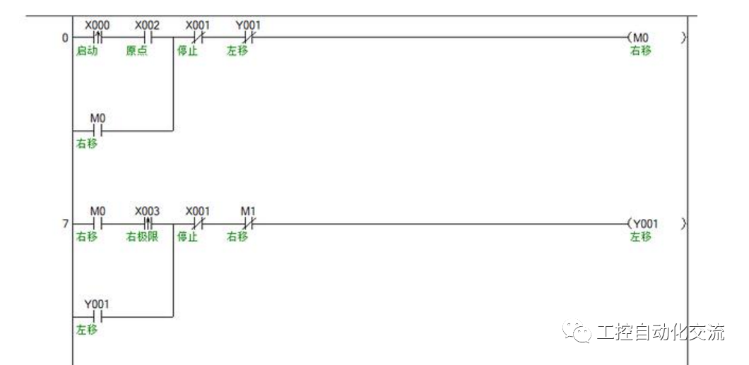
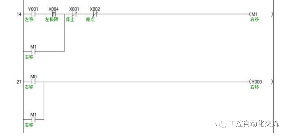
The PLC’s job is to execute the sequential control program, and using simple ladder diagrams or SFC (Sequential Function Chart) can achieve this continuous action control, and the programming is straightforward and intuitive.