All brands of PLCs have self-diagnostic functions, but the skill in PLC repair lies in fully utilizing this function for analysis and accurately identifying the problem. Here are eight common error types that PLC repair personnel need to understand when the PLC presents abnormal alarms.
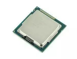
01Abnormal CPU
When an abnormal CPU alarm occurs, check all devices connected to the internal bus of the CPU unit. The specific method is to sequentially replace the potentially problematic units to identify the faulty unit and take appropriate action.
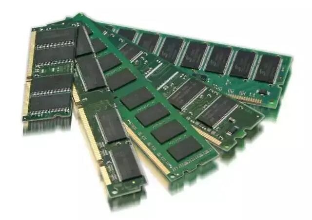
 02Abnormal Memory
When an abnormal memory alarm occurs, if the issue is with the program memory and reprogramming does not resolve it, this situation may be caused by noise interference altering the program; otherwise, the memory should be replaced.
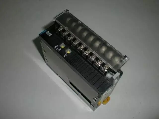
 03Abnormal Input/Output Units, Abnormal Expansion Units
When this type of alarm occurs, first check the connection status of the input/output units and expansion unit connectors, as well as the cable connections. After determining which unit the problem has occurred in, replace that unit.
 04Program Not Executing
Generally, the inspection can follow the process of input – program execution – output.
(1) Input inspection is done using the input LED indicators or an input monitor created by a programmer. When the input LED is not lit, it can be initially determined that there is an issue with the external input system, and a multimeter can be used for further inspection. If the output voltage is abnormal, it can be determined that there is an issue with the input unit. When the LED is lit but the internal monitor shows no display, it can be considered a problem with the input unit, CPU unit, or expansion unit.
(2) Program inspection is done through the monitor on the programmer. If the status of the ladder diagram contacts does not match the results, it indicates a program error (e.g., using internal relays in two layers) or an issue in the calculation section.
(3) Output inspection can be done using output LED indicators. If the calculation result is correct but the output LED indicates an error, it can be considered a problem with the CPU unit or I/O interface unit. If the output LED is lit but there is no output, it can be determined that there is an issue with the output unit or the external load system.
Due to different PLC models, the connection methods for I/O and LEDs vary (some connect to the I/O unit interface, while others connect to the I/O unit itself). Therefore, the scope of issues determined by the LED also varies.
05Partial Program Not Executing
The inspection method is the same as the previous item; however, if the input timing for counters, step controllers, etc., is too short, a non-response issue may occur. In this case, the input timing should be verified to ensure it is sufficiently large, which can be checked based on the relationship of input timing (maximum response time of the input unit + calculation scan time multiplied by 2).
 06Power Short-Circuit or Power Loss, Program Content May Disappear
(1) First, check if there is an issue with the battery.
(2) Check by repeatedly turning the PLC power on and off; to ensure the microprocessor starts correctly, the PLC has a reset point circuit and a program retention circuit when the power is disconnected. If there is an issue with this circuit, the program cannot be retained, so the power on and off can be used for inspection.
(3) If the abnormal battery alarm persists after replacing the battery, it can be determined that the issue is caused by abnormal leakage current in the memory or external circuit.
(4) The power on and off always occurs synchronously with the machine system. At this time, the noise impact from the machine system can be checked. Since the power disconnection often occurs simultaneously with the machine system operation, it is mostly caused by strong noise generated by motors or windings.
07PROM Not Functioning
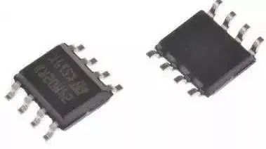
First, check if the PROM connection is good, then determine if the chip needs to be replaced.
 08Action Stops After Power Restart or Reset
This issue can be considered as caused by noise interference or poor internal contact of the PLC. The noise is generally caused by the reduction of small capacitor capacity on the circuit board or malfunctioning components. For poor contact issues, gently tapping the PLC body can be used for inspection, and the connection status of cables and connectors should also be checked.
Disclaimer:This article is reproduced from the internet, and the copyright belongs to the original author. If there are any copyright issues, please contact us promptly for deletion. Thank you!