“SDO is responsible for telling the drive how to work, while PDO is responsible for keeping the drive working continuously.”—— Essence of understanding from a bald engineer
If you have understood SDO, then congratulations, you are just one step away from “making the motor really move” — PDO.
PDO is the soul of the entire CANopen control. The speed, position, and current commands you write must be implemented through PDO for real-time control.
This article will thoroughly explain:
-
What is PDO?
-
What is the difference between TPDO and RPDO?
-
What does mapping actually map?
-
Why do some drives “not respond when speed is written”?
-
What is the impact of SYNC on PDO?
-
How to configure a usable PDO?
-
How to achieve multi-axis synchronization for AGV/robot arms?
After reading, you will fully master PDO.
🟧 1. What is PDO? Explained in one sentence
PDO (Process Data Object) is used for high-speed real-time transmission of “process data”.
It is specifically designed for “real-time control”:
✔ Speed command✔ Position command✔ Current command✔ Actual speed feedback✔ Actual position feedback✔ Status word✔ Control word
These are all “process data” and must use PDO.
🟧 2. There are two types of PDO: TPDO (Upload) vs RPDO (Download)
| Type | Direction | Function |
|---|---|---|
| TPDO | Slave → Master | Feedback: Position, Speed, Status word |
| RPDO | Master → Slave | Commands: Control word, Speed, Position |
The COB-ID for these two is:
-
TPDO1: 0x180 + NodeID
-
RPDO1: 0x200 + NodeID
For example: Node 8
-
TPDO1 = 0x188
-
RPDO1 = 0x208
These are the two you will most commonly encounter when capturing messages.
🟧 3. The core concept of PDO: Mapping
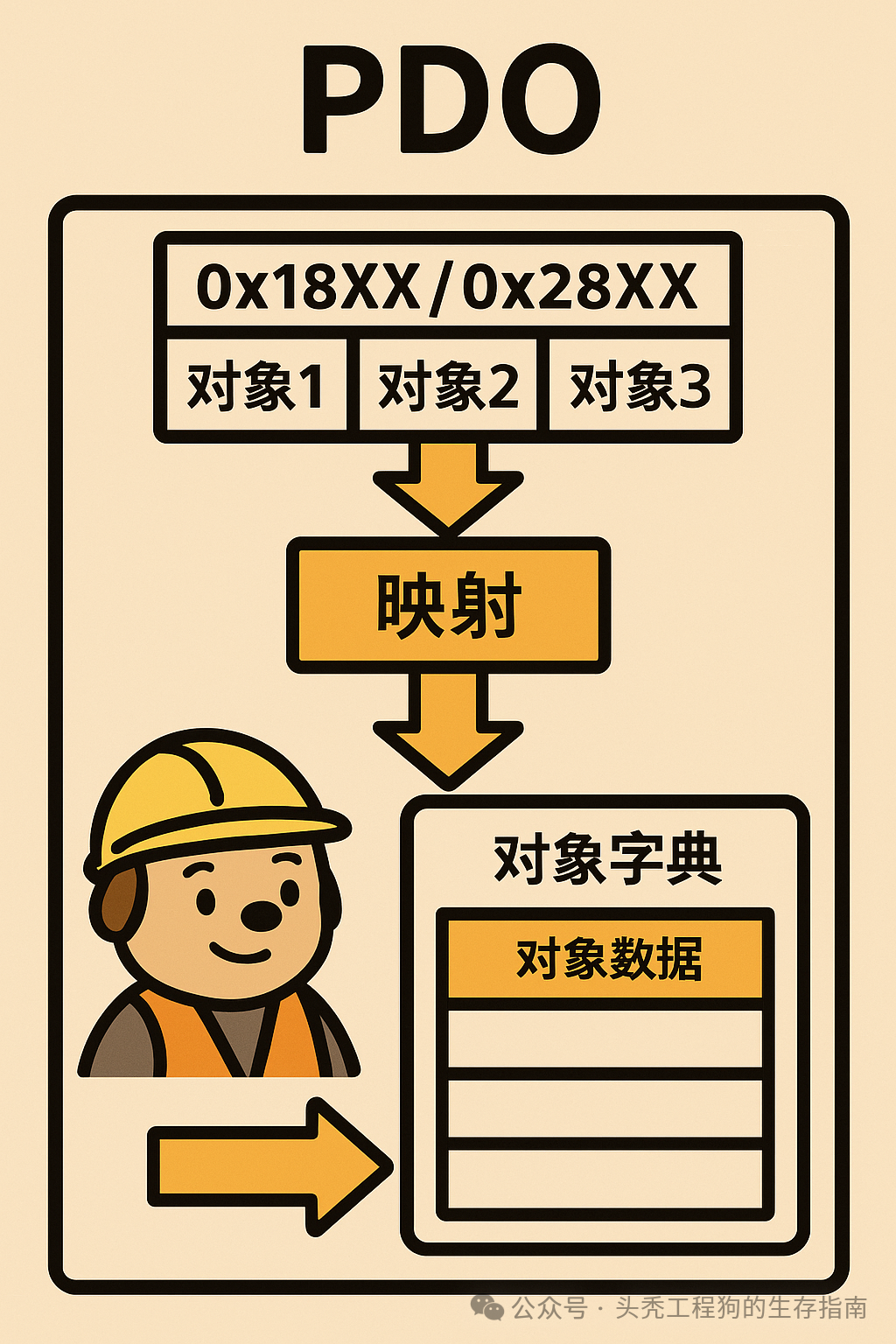
Many people get stuck on Mapping, but it can be explained in one sentence:
Mapping is telling the drive: In these 8 bytes of PDO, which objects do you want to place? In what order?
For example, if you want:
RPDO1 Byte 1~Byte 2: 6040 (Control word) RPDO1 Byte 3~Byte 6: 60FF (Speed)Then:
-
6040 maps to 16bit
-
60FF maps to 32bit → Total 48bit (6 bytes)
Leaving 2 bytes empty.
Mapping is about these.
🟧 4. Steps to configure PDO mapping (Standard Process)
This is the most common pitfall with PDO,you must first disable → map → then enable.
Taking RPDO1 as an example:
✔ Step 1: Disable PDO
0x1400 sub1 = 0
0x1400 sub1 = 0✔ Step 2: Clear mapping
0x1600 sub0 = 0✔ Step 3: Write mapping object list
For example:
-
6040: 16 bit → Write 0x60400010
-
60FF: 32 bit → Write 0x60FF0020
0x1600 sub1 = 0x60400010 0x1600 sub2 = 0x60FF0020✔ Step 4: Write mapping count (sub0)
0x1600 sub0 = 2 # 2 mapping objects✔ Step 5: Re-enable PDO0x1400 sub1 = COB-ID (e.g., 0x200+NodeID)This process must be memorized,
90% of PDO configuration failures are due to incorrect order.
🟧 5. PDO Transmission Types
There are 3 transmission modes for PDO:
✔ 1) Synchronous (requires SYNC)
Transmission Type = 1~240
The master sends SYNC (0x80) at fixed intervals:
For example, every 10ms:
SYNC → RPDO → TPDO → Synchronous occurrenceAGV dual-wheel and multi-axis robotic arms must use synchronous mode.
✔ 2) Asynchronous (event-triggered)
Transmission Type = 255
Send immediately when data changes:
-
TPDO: Speed change, Position change
-
RPDO: Execute immediately after the drive receives it
Suitable for: Single-axis or asynchronous scenarios.
✔ 3) Periodic Trigger (event count)
Configure event count, for example:
Transmission Type = 5 → Trigger PDO only after receiving 5 SYNCs.
Suitable for: Saving bandwidth, low-frequency status updates.
🟧 6. Impact of SYNC on PDO (Key)
If your drive is in synchronous mode:
-
No SYNC → The motor will not move
-
SYNC cycle too slow → Motor action is jerky
-
Unstable SYNC → Jitter, delay, desynchronization
Common issues with AGV dual wheels:
-
“The angles of the left and right wheels do not match”
-
“Inconsistent speed leads to deviation”
90% of the time it is because:
-
SYNC is not using hard timing
-
SYNC DP is missing, delayed, or jittery
-
PDO configuration is asymmetric
🟧 7. Practical: Configuring a usable RPDO (Speed Control)
Objective: The master writes to Node 8 via RPDO1:
-
Control word (6040)
-
Target speed (60FF)
✔ Configuration Example (SDO Writing)
# Disable RPDO1 node.sdo[0x1400][1].raw = 0 # Clear Mapping node.sdo[0x1600][0].raw = 0 # Map 6040 (16bit) node.sdo[0x1600][1].raw = 0x60400010 # Map 60FF (32bit) node.sdo[0x1600][2].raw = 0x60FF0020 # Write sub0 = 2 node.sdo[0x1600][0].raw = 2 # Enable RPDO1 (COB-ID) node.sdo[0x1400][1].raw = 0x200 + 0x08# Send speed command (PDO) pdo = node.rpdo[0] pdo['Controlword'].raw = 0x0F pdo['Target velocity'].raw = 1000 pdo.transmit() → The motor immediately starts rotating.🟧 8. Practical: Configuring TPDO (Speed and Status Word Feedback)
Typical mapping:
-
6041: 16bit (Status word)
-
606C: 32bit (Actual speed)
Similarly for Mapping.
🟧 9. How to achieve AGV / Multi-axis synchronization?
-
The master periodically sends SYNC (high-precision timer)
-
All drives are configured for synchronous mode
-
All RPDO / TPDO mappings are consistent
-
All motors update commands at the same SYNC moment
-
Read TPDO feedback for real-time synchronization status
The control of AGV’s steering wheel uses this principle.
🟧 10. Engineer’s Pitfall Summary (Very Important)
❌ 1) Mapping without disabling PDO
→ Guaranteed failure
❌ 2) sub0 not cleared to 0 first
→ Also guaranteed failure
❌ 3) Asymmetric mapping of RPDO and TPDO
→ Different angles during synchronization
❌ 4) Unstable SYNC
→ Severe deviation, jitter
❌ 5) PDO length exceeds 8 bytes
→ Directly reports 0604 0042
❌ 6) Incorrect object mapping (e.g., mapping 6041 into RPDO)
→ The motor will directly alarm
🟦 Next Article Preview (Part 7)
How to correctly configure PDO (Disable → Clear sub0 → Write mapping → Write sub0 → Enable)