
Common Issues
1. Does S7-200 SMART support Modbus ASCII communication mode?
The STEP 7-Micro/WIN SMART software does not provide a command library for Modbus ASCII communication mode. If the S7-200 SMART CPU is used for Modbus ASCII communication, the user needs to program using the free port communication mode.
2. Can the integrated RS485 port (Port 0) of the S7-200 SMART CPU and the SB CM01 signal board (Port 1) function simultaneously as Modbus RTU masters or as Modbus RTU slaves?
The S7-200 SMART V2.2 version supports both communication ports to function as MODBUS RTU masters simultaneously but does not support them to function as MODBUS RTU slaves at the same time.
3. How does the S7-200 SMART CPU, as a Modbus RTU master, access holding registers with addresses greater than 49999?
Typically, the holding register range of the Modbus protocol is between 40001 and 49999, which is sufficient for most applications. However, some Modbus slaves may have holding register addresses that exceed this range. The Modbus RTU master protocol library supports holding register address ranges of (40001 to 49999) or (400001 to 465536). If the Modbus slave address range is 400001 – 465536, simply assign the corresponding value to the Addr parameter when calling the MBUS_MSG subroutine, such as 416768.
4. Why does the MBUS_MSG instruction return error code 6# when the S7-200 SMART CPU, as a Modbus RTU master, calls the MBUS_MSG instruction multiple times?
Only one MBUS_MSG instruction can be active at the same time. If multiple MBUS_MSG instructions are activated, the first MBUS_MSG instruction will execute, and all subsequent MBUS_MSG instructions will be aborted and return error code 6#. The execution of multiple MBUS_MSG instructions needs to be done in a polling manner.
5. When the S7-200 SMART CPU, as a Modbus RTU master, encounters a slave failure or communication line disconnection, it attempts to send multiple request messages, resulting in excessive communication time. How can the master reduce the number of retries to improve communication efficiency?
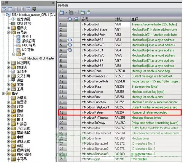
When the MBUS_MSG instruction is activated, it sends a Modbus request message frame. If the master does not receive a response from the slave within the time interval defined by the Timeout parameter, the Modbus RTU master protocol library will, by default, send 2 more Modbus request message frames. After the last request message frame is sent, if no response is received after the time interval defined by the Timeout parameter, the Done bit of the MBUS_MSG instruction will only be set to 1. To cancel the retry count of the Modbus request message frame, set the value of the mModbusRetries variable from 2 to 0. The absolute address of the mModbusRetries variable can be obtained by querying the symbol table of the Modbus RTU master protocol library, as shown in Figure 1. The Modbus RTU master command symbol table.
6. Why can some HMI software using the Modbus RTU protocol read data from the S7-200 SMART CPU as a Modbus RTU slave, but cannot write data?
This may be because the software uses Modbus function 15 to write multiple digital outputs to the S7-200 SMART CPU without adhering to the slave protocol that requires starting at byte-aligned addresses (such as Q0.0, Q2.0) and using a count of bits that is a multiple of 8. Ensuring that the HMI software strictly follows this rule can prevent write errors.
7. Why does some HMI software using the Modbus RTU protocol encounter errors when reading floating-point data from the S7-200 SMART CPU as a Modbus RTU slave?
This may occur because the HMI software processes the storage format of floating-point numbers in holding registers differently from Siemens’ floating-point storage format. Siemens’ PLC follows the convention of “high byte low address, low byte high address”.
Holding registers in Modbus RTU are organized by “words”, with 1 floating-point data consisting of 2 “words”. The HMI software may swap the positions of the two “words” in the holding registers, causing it to fail to recognize the floating-point number represented in Siemens format. If one side of the HMI software cannot handle this floating-point number, programming can be done in the S7-200 SMART CPU to swap the high and low “words” stored in the holding register area.
8. When the S7-200 SMART compact CPU is used as a Modbus RTU slave, and the MBUS_INIT instruction’s Mode input parameter has been set to “1”, why does the MBUS_SLAVE instruction still return error code 10 (slave function not enabled)?
The S7-200 SMART compact CPU cannot expand signal modules and does not have analog input channels. If the MaxAI input parameter of the MBUS_INIT instruction is not set to “0”, the MBUS_SLAVE instruction will return error code 10.
9. Does the S7-200 SMART CPU as a Modbus RTU slave support broadcast commands sent by the Modbus RTU master?
The S7-200 SMART CPU as a Modbus RTU slave does not support broadcast commands.
Master Fault Codes
|
MBUS_CTRL Error Code |
Description |
|---|---|
|
0 |
No Error |
|
1 |
Invalid Parity Type |
|
2 |
Invalid Baud Rate |
|
3 |
Invalid Timeout |
|
4 |
Invalid Mode |
|
9 |
Invalid Port Number |
|
10 |
Signal Board Port 1 Missing or Not Configured |
Slave Fault Codes
|
MBUS_MSG Error Code |
Description |
|---|---|
|
0 |
No Error |
|
1 |
Response Has Parity Error: This error occurs only when using even or odd parity. The transmission is disturbed, and incorrect data may be received. This error is usually caused by electrical faults (e.g., wiring errors or electrical noise affecting communication). |
|
2 |
Not Used |
|
3 |
Receive Timeout: The slave did not respond within the timeout period. Possible reasons include: electrical connection issues with the slave device, different baud rate/parity settings between master and slave, or incorrect slave address. |
|
4 |
Request Parameter Error: One or more input parameters (“Slave”, “RW”, “Addr”, or “Count”) are set to illegal values. For information on allowable values for input parameters, please refer to this document. |
|
5 |
Modbus Master Not Enabled: Call MBUS_CTRL before calling MBUS_MSG on each scan. |
|
6 |
Modbus Busy Processing Another Request: Only one MBUS_MSG instruction can be active at a time. |
|
7 |
Response Error: The received response does not match the request, indicating a problem with the slave device or that an incorrect slave device responded to the request. |
|
8 |
Response Has CRC Error: The transmission is disturbed, and incorrect data may be received. This error is usually caused by electrical faults (e.g., wiring errors or electrical noise affecting communication). |
|
11 |
Invalid Port Number |
|
12 |
Signal Board Port 1 Missing or Not Configured |
|
101 |
Slave Does Not Support Requested Function for Address: See the required Modbus slave function support table in the help topic “Using Modbus Master Instructions”. |
|
102 |
Slave Does Not Support Data Address: The request address range of “Addr” plus “Count” exceeds the allowable address range of the slave. |
|
103 |
Slave Does Not Support Data Type: The slave device does not support the “Addr” type. |
|
104 |
Slave Device Fault |
|
105 |
Slave Accepted Message but Did Not Respond in Time: MBUS_MSG Error occurred, user program should resend the request later. |
|
106 |
Slave Busy, Message Rejected: The same request can be retried to get a response. |
|
107 |
Slave Rejected Message for Unknown Reasons. |
|
108 |
Slave Memory Parity Error: The slave device has a fault. |
Modbus RTU Slave Execution Error Codes
|
Error Code |
Description |
|---|---|
|
0 |
No Error |
|
1 |
Memory Range Error |
|
2 |
Invalid Baud Rate or Parity |
|
3 |
Invalid Slave Address |
|
4 |
Illegal Modbus Parameter Value |
|
5 |
Holding Register Overlap with Modbus Slave Symbol |
|
6 |
Received Parity Error |
|
7 |
Received CRC Error |
|
8 |
Illegal/Unsupported Function Request |
|
9 |
Illegal Memory Address in Request |
|
10 |
Slave Function Not Enabled |
|
11 |
Invalid Port Number |
|
12 |
Signal Board Port 1 Missing or Not Configured |
Source: Internet, copyright belongs to the original author. If there is any infringement, please contact for deletion.
View more 
Click“Read Original“,Learn about electrical engineering, PLC, and other knowledge