Serial cables are divided into straight-through and crossover types. Straight-through cables are generally used to extend connections between a PC and a device, connecting pins 2, 3, and 5 to pins 2, 3, and 5 respectively. This is because PCs usually have male connectors while devices often have female connectors, making them universally compatible for both extension and direct connection. Crossover cables are typically used for direct connections between PCs, connecting pin 2 to pin 3, pin 3 to pin 2, and pin 5 to pin 5; usually both ends are female connectors!
Before the advent of computers, the EIA established the RS232 standard for connecting serial devices. After the introduction of PCs, existing serial devices became peripherals for PCs, naturally adopting the RS232 standard. Currently, the serial communication interface for PCs uses the EIA-RS-232C standard, with C representing the latest revision in 1969. The EIA-RS-232C standard specifies the electrical characteristics, logic levels, and functions of various signal lines. The EIA-RS-232C standard uses positive and negative voltages to represent logical states; if the voltage on the data signal line is between -3V and -15V, it represents logic 1, while a voltage between +3V and +15V represents logic 0. On control signal lines, a voltage between -3V and -15V indicates an open state, while a voltage between +3V and +15V indicates a closed state. Voltages between -3V and +3V, as well as below -15V or above +15V, are meaningless.
The CPU and terminals, on the other hand, use TTL levels and positive logic, where TTL levels represent logic 1 with +5V and logic 0 with 0V. These are incompatible with the levels and negative logic used by EIA, requiring conversion in the interface circuitry. The EIA-RS-232C standard does not define the physical characteristics of connectors, leading to various types of connectors such as DB-25, DB-15, and DB-9. The COM1 and COM2 serial interfaces of PCs use DB-9 connectors. The EIA-RS-232C standard allows a wire length of 15m when the error rate is below 4%. In practical applications, when using 9600 b/s and ordinary twisted shielded cables, transmission distances can reach 30m to 35m. The DB-9 connector used for the COM1 and COM2 serial interfaces of PCs is a male (pin) connector, providing asynchronous communication functionalities across 9 pins, which are: ① pin (DCD) Data Carrier Detect, ② pin (RXD) Receive Data, ③ pin (TXD) Transmit Data, ④ pin (DTR) Data Terminal Ready, ⑤ pin (SG) Signal Ground, ⑥ pin (DSR) Data Set Ready, ⑦ pin (RTS) Request to Send, ⑧ pin (CTS) Clear to Send, ⑨ pin (RI) Ring Indicator. The pin arrangement for the DB-9 male (pin) connector is shown on the left, while the arrangement for the DB-9 female (socket) connector is shown on the right. Note that the pin numbers for the male connector are counted from left to right, while for the female connector, they are counted from right to left. In the EIA-RS-232C standard, there are three transmission signals: TXD, RTS, and DTR, with a typical output current of ±8mA/±12V for each line. Typically, if powered by RTS and DTR, it can provide approximately 192mW of power.
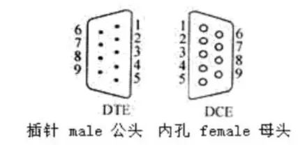
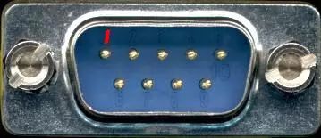
The PC side is generally a male connector, as shown in the image.
Based on the above explanation, if a modem is not involved, serial data transmission only requires the receiving data pin (pin ②) and the transmitting data pin (pin ③) to connect. You should connect the receiving data pin of one device to the transmitting data pin of another device, meaning that the receive and transmit lines are crossed, while the signal ground should be connected correspondingly.
Question 1: When to use crossover and when to use straight-through?
The standard serial port pin 2 is RX and pin 3 is TX (i.e., the 2nd pin of the 9-pin serial port connects to the RXD pin of the main control chip, and the 3rd pin connects to the TXD pin of the main control chip). If both the microcontroller development board’s serial port and the computer’s serial port are standard serial ports, then the two serial ports should be connected using a crossover cable. However, in reality, straight-through cables are more common (possibly because straight-through cables are easier to produce than crossover cables). To accommodate the use of straight-through cables, when designing the circuit board, connect the RXD pin of the main control chip to pin 3 of the serial port, and the TXD pin of the main control chip to pin 2 of the serial port. This way, the serial port on this development board is no longer a standard serial port, meaning pin 2 becomes TX and pin 3 becomes RX, so a straight-through cable should be used when connecting to a standard serial port. To determine whether a serial port on a development board is standard or non-standard, one must look at the schematic to see how it is connected!
In summary: The RS232 DB-9 connector cables include three types: male to female, male to male, and female to female. Each of these three types has both crossover and straight-through variants, resulting in a total of six connection methods.
Question 2: How to distinguish between crossover and straight serial cables?
Use a multimeter to check; if pins 2 and 2 connect and pins 3 and 3 connect, it is a straight-through serial cable; if pins 2 and 3 connect and pins 3 and 2 connect, it is a crossover serial cable.
Some may be confused because the female connector has an insulating rubber outside, making it difficult for the multimeter probe to be inserted. In that case, you can cut a small piece of solder wire (I once considered using metal wire, but it is too thin and we cannot guarantee it will make good contact with the metal part inside the female connector. Solder wire is thicker and can make good contact with the metal inside the female connector), and then touch the multimeter probe to the solder wire to test it.
Of course, if you have to use a multimeter every time you get a serial cable to check whether it is straight-through or crossover, it would be very inconvenient. Here’s an easy way to tell: if both ends are female connectors, it is a crossover cable; if one end is male and the other is female, it is a straight-through cable. (It seems that serial cables with both ends male are very rare.)
Note: It is strongly recommended not to connect or disconnect serial ports while powered on; at least one end should be powered off, otherwise the serial port may be damaged.


To help everyone learn better, Changxue Electronics has specially added a public account focused on microcontrollers and EDA, pushing related knowledge daily. We hope it can assist you in your studies!