Simulation Modeling of HERIC Photovoltaic Inverter Based on Matlab/SimulinkKeywords: Photovoltaic Cells, Matlab/Simulink, Simulation ModelingSimulation Platform: MATLAB/SimulinkMain Content: This article builds a HERIC photovoltaic inverter topology using photovoltaic cells as the power source on the Matlab/Simulink platform, successfully converting DC to AC using sine and triangle wave-driven MOSFET switches.
The following article and example code are for reference only.
In distributed photovoltaic power generation systems, photovoltaic inverters serve as the key devices connecting the DC side (photovoltaic array) with the AC grid. Their topology directly affects system efficiency, reliability, and power quality. HERIC (Highly Efficient and Reliable Inverter Concept) is a single-phase non-isolated inverter topology with low leakage current and high conversion efficiency advantages, widely used in residential photovoltaic scenarios.
This article establishes a complete HERIC photovoltaic inverter simulation model based on the MATLAB/Simulink platform, using photovoltaic cells as the DC power source and employing a Sine Pulse Width Modulation (SPWM) strategy to drive MOSFET switches, successfully achieving efficient DC to AC conversion and verifying its basic working principles and output characteristics.
1. Introduction to HERIC Topology
The HERIC inverter adds two high-frequency switches (typically S5 and S6) and their anti-parallel diodes to the traditional full-bridge inverter, forming an additional freewheeling loop. Its core advantages include:cutting off the common-mode loop between the photovoltaic panel and the grid during the freewheeling phase, significantly suppressing leakage current;all switching devices operate at line frequency or high frequency, facilitating control;no line frequency transformer is required, resulting in a compact system, lower costs, and higher efficiency.
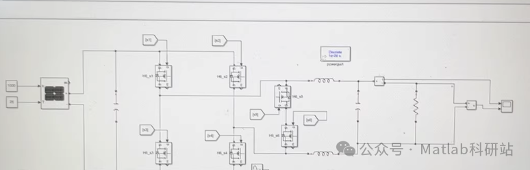
The typical topology is shown in the figure below (the article can include a screenshot of the Simulink model):DC Side: Photovoltaic Cells (DC Source)Main Bridge Arm: S1–S4 (Line Frequency Switches)Freewheeling Bridge Arm: S5–S6 (High Frequency Switches)Output Filtering: LC Filter + AC Load/Grid
2. Building the Simulink Model
- Photovoltaic Power ModuleUse the Controlled Voltage Source in Simulink to simulate the output of photovoltaic cells, setting the open-circuit voltage to 400 V and the maximum power point voltage to approximately 360 V. A more detailed PV Array module (requires Simscape Electrical) can also be used to simulate I-V characteristics.
- Main Circuit of the InverterConstruct a six-switch HERIC topology using MOSFET or IGBT modules (recommended to use Universal Bridge or discrete construction);set dead time to prevent shoot-through;add an LC filter (L = 2 mH, C = 2.2 μF) to filter out high-frequency harmonics.
- Generating Drive Signals (SPWM Control)Use the classic sine-triangle comparison method to generate PWM signals:Modulation Wave: 50 Hz sine wave (amplitude adjustable for controlling output voltage);Carrier: 5 kHz triangle wave;Compare using the Relational Operator module to generate PWM logic;Based on the HERIC operating mode, reasonably allocate the driving timing for S1–S6 (see the table below).
Operating Interval S1 S2 S3 S4 S5 S6
Positive Half Cycle ON OFF OFF ON OFF OFFPositive Half Cycle Freewheeling OFF OFF OFF OFF ON ONNegative Half Cycle ON OFF OFF OFF OFF OFFNegative Half Cycle Freewheeling OFF OFF OFF OFF ON ON⚠️ Note: During the freewheeling phase, S5 and S6 are simultaneously turned on, forming a freewheeling path isolated from the photovoltaic side and the load side, which is key to suppressing common-mode leakage current.
3. Simulation Results and Analysis
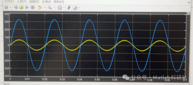
Set the simulation time to 0.1 seconds, using the ode23tb solver (suitable for power electronic systems), with key waveforms as follows:
- Output Voltage and CurrentThe inverter outputs a 50 Hz sine AC voltage, with THD < 3% after LC filtering;with a resistive load (e.g., 220 V / 1 kW), the current and voltage are in phase, and the power factor is close to 1.
- Switching Device Drive SignalsS1/S4 and S2/S3 alternate in line frequency conduction;S5/S6 synchronously conduct during the zero level interval of each PWM cycle, achieving passive freewheeling.
- DC Side Current RippleSince the freewheeling loop does not pass through the photovoltaic side, the DC current is continuous with low ripple, which is beneficial for stable operation of the photovoltaic MPPT.📊 Example waveforms (to be replaced with Scope screenshots upon actual publication):Top Figure: AC Output Voltage (blue), Current (red)Bottom Figure: Timing of S1–S6 Drive Signals
4. Summary of Advantages
Through this simulation verification, the HERIC topology demonstrates the following characteristics:✅ Successfully achieves DC→AC conversion with good output power quality;✅ Effectively isolates the DC side from the AC side during the freewheeling phase, naturally suppressing leakage current;✅ Clear control logic, easy to implement on DSP or FPGA;✅ Suitable for small to medium power (1–10 kW) photovoltaic grid-connected systems.
5. Conclusion and Outlook
This article completed the modeling and simulation of the HERIC photovoltaic inverter based on MATLAB/Simulink, verifying its basic functionality and control strategy effectiveness. This model can be further expanded:by adding MPPT control algorithms (such as P&O, INC) for maximum power tracking;integrating grid synchronization control (such as PLL, current closed-loop);conducting efficiency analysis and thermal simulation to assess actual losses.💡 Tip: A complete Simulink model (.slx file) can be organized and provided based on learning and research needs; feel free to leave comments for discussion!