
In the field of electronic engineering design, efficiency and precision are the keys to success. The “golden combination” of MATLAB and Simulink, with their deeply integrated functionalities and wide applicability, has long become the “right-hand man” for engineers.
From control systems to signal processing, from image processing to industrial automation, from chip design to FPGA development, they span multiple core areas of electronic design, making complex R&D processes efficient and controllable.
Today, we will provide a comprehensive analysis of the specific applications of these two tools in various fields of electronic design, especially focusing on core technical aspects in control system design and chip, FPGA development.
1. Understanding the “Special Relationship” between MATLAB and Simulink Many people may wonder if MATLAB and Simulink are two independent software packages. The answer is no. – MATLAB is a commercial mathematical software developed by MathWorks, integrating functionalities such as algorithm development, data analysis, and matrix computation, serving as a multifunctional scientific computing platform. – Simulink, on the other hand, is a visual simulation tool within MATLAB, centered around a block diagram environment, focusing on multi-domain simulation and model-based design. The two are deeply integrated: Simulink can directly call MATLAB algorithms, and simulation results can be exported to MATLAB for further analysis, forming a complete closed loop of “design-simulation-analysis-deployment,” providing full-process support for electronic design.
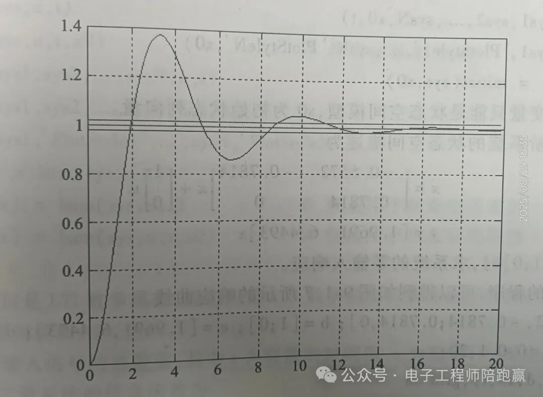
2. Covering Multiple Domains: The “Effective Assistant” in Various Stages of Electronic Design 1. Control System Design: Full Process Support from Theory to Implementation In control system design, MATLAB and Simulink cover almost all key stages from modeling to deployment, serving as core tools for power electronics engineers developing digital control systems for motors, power converters, battery systems, etc.: – Control System Modeling: MATLAB provides system identification tools (such as the System Identification Toolbox) to construct controlled object models from measured data; it also supports physical modeling, directly deriving transfer functions or state equations based on principles of circuits, mechanics, etc. Simulink allows intuitive construction of multi-domain (electrical, mechanical, hydraulic, etc.) system models through modular drag-and-drop, significantly lowering the modeling threshold without manual derivation of formulas. – Time Domain Analysis: Directly simulate step response and impulse response of control systems, automatically calculating key indicators such as overshoot, settling time, and peak time. For example, in motor speed control system design, the step() function in MATLAB or the oscilloscope module in Simulink can quickly observe the dynamic changes in speed with input commands, assessing system stability.
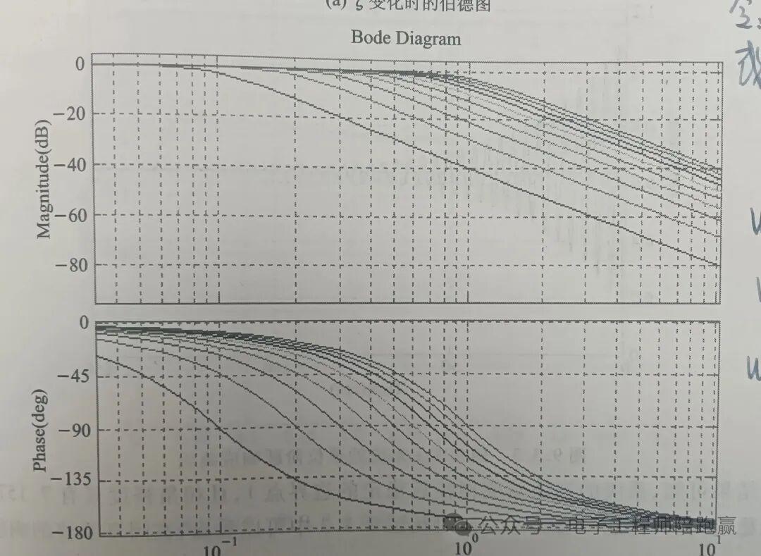
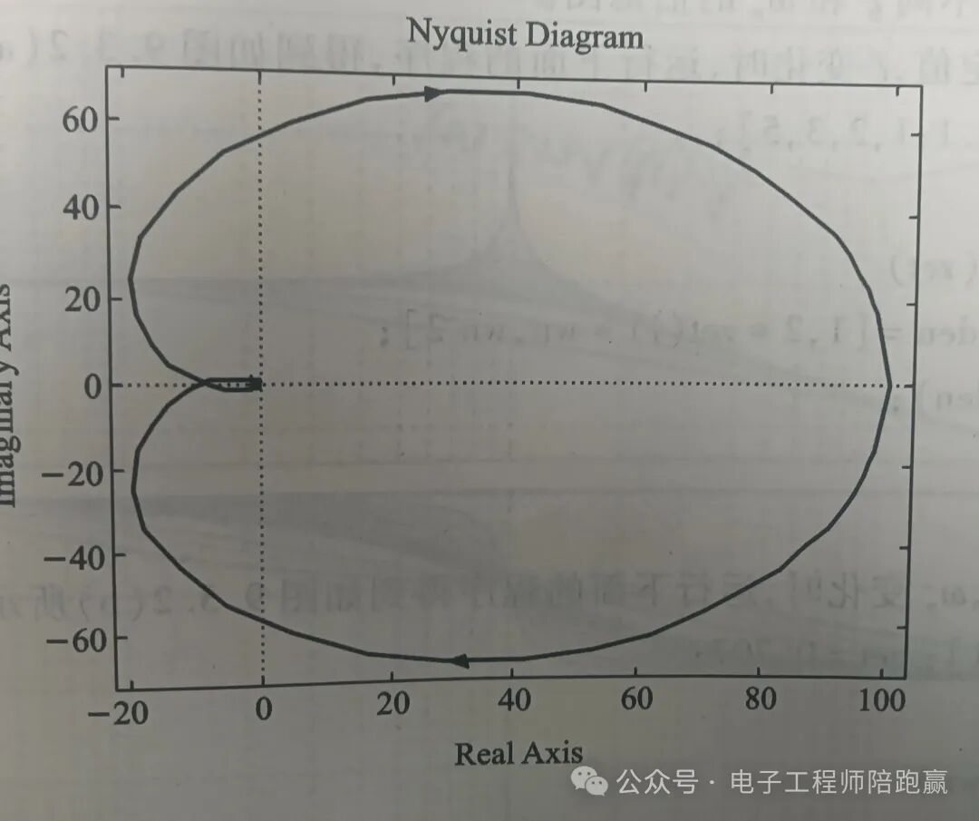
– Frequency Domain Analysis: Built-in tools such as Bode Diagram and Nyquist Plot can generate system amplitude and phase characteristics with one click, easily determining system gain margin, phase margin, and assessing stability and dynamic performance. In filter design, frequency domain analysis can visually verify filtering effects.
– Root Locus Analysis: Using MATLAB’s rlocus() function or Simulink’s root locus module, plot the root locus diagram of the system, clearly showing how closed-loop poles change with parameters (such as open-loop gain), helping engineers adjust parameters to place poles in desired locations and optimize system response.
– System Calibration: Supports classic calibration methods such as Proportional-Integral-Derivative (PID) and lead-lag compensation, providing automatic calibration tools (such as PID Tuner) that can automatically calculate calibration device parameters based on system performance indicators (such as overshoot, response speed) and verify calibration effects through simulation, quickly resolving issues of system stability or dynamic performance inadequacies. – Discrete System Analysis: For digital control systems, perform z-transformation and impulse transfer function analysis on discrete transfer functions, using the unit circle criterion to determine stability, simulating the step response of discrete systems, and assessing the impact of sampling periods on system performance, ensuring the accuracy of digital controller design.
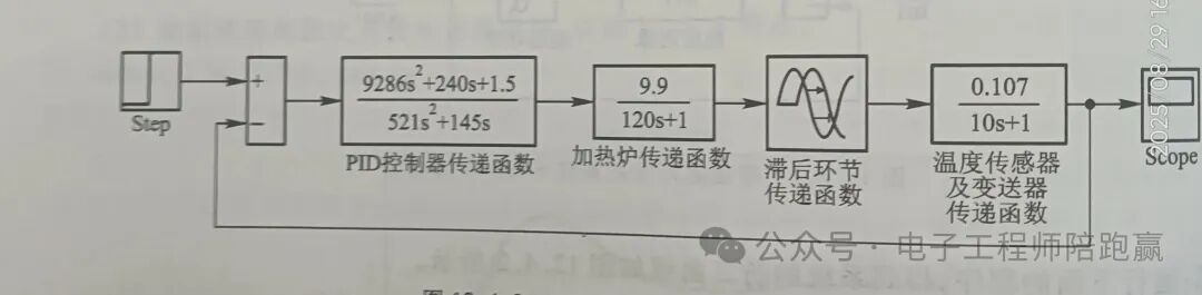
– Nonlinear Control Analysis: For systems with nonlinear elements such as saturation, dead zones, and friction, Simulink can directly build nonlinear modules, analyzing nonlinear phenomena such as system oscillation using phase plane methods and describing function methods, while MATLAB provides numerical solving tools for nonlinear systems, avoiding the complexity of manual derivation.
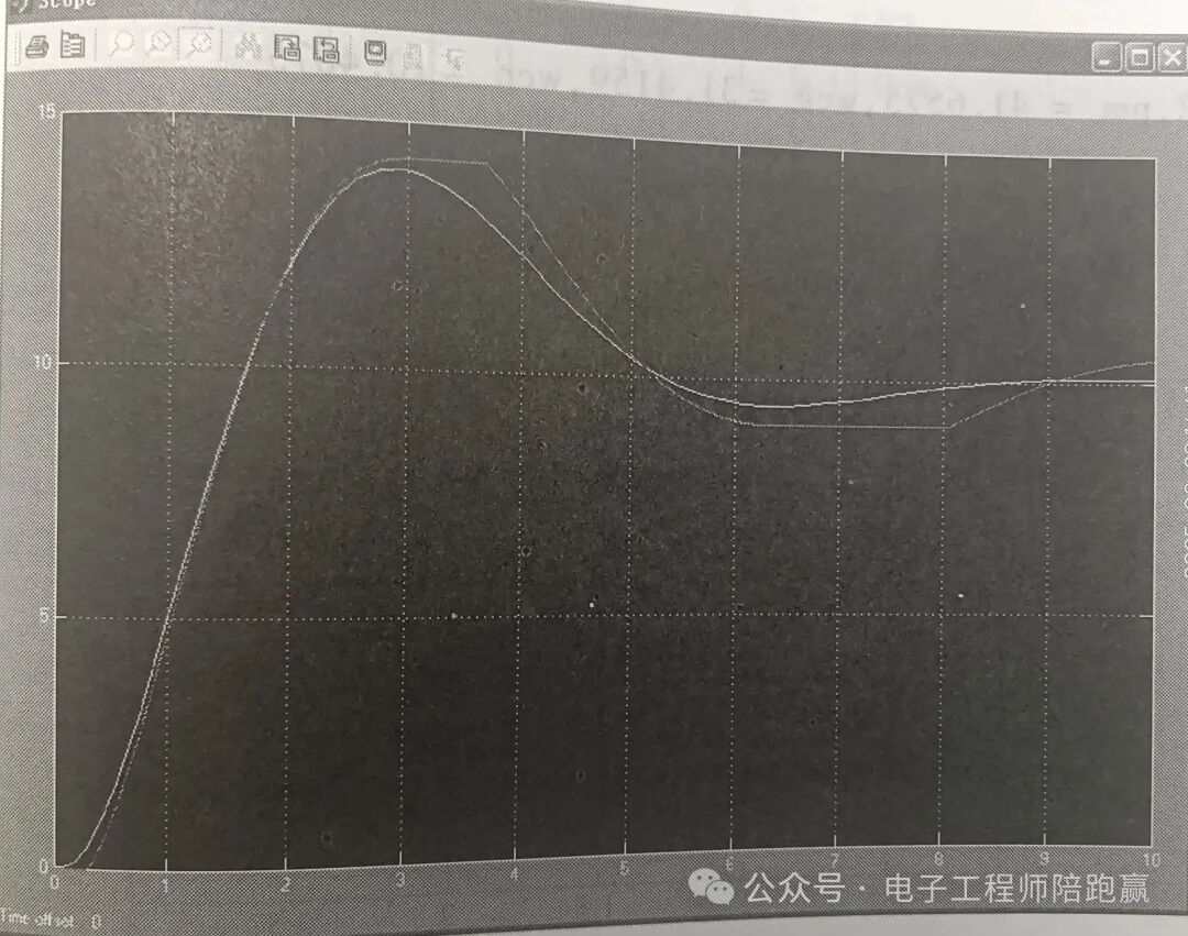
– State Space Analysis: Supports describing systems in state equation form, using MATLAB’s matrix computation tools to calculate system controllability and observability, plotting state trajectories, providing a basis for controller design (such as state feedback). In multi-input multi-output (MIMO) systems, state space methods are particularly efficient. – Optimal Control: Built-in optimal control design tools such as Linear Quadratic Regulator (LQR) and Linear Quadratic Gaussian (LQG) can automatically solve optimal control laws based on system performance indicators (such as minimizing error, minimizing energy consumption). For example, in drone attitude control, the LQR algorithm can achieve rapid stabilization of attitude and energy optimization. – Simulink Modeling and Simulation: As the core of visual simulation, Simulink provides a rich library of control system modules (such as controllers, sensors, actuators), supporting continuous, discrete, and hybrid system simulations. Engineers can build closed-loop control systems by dragging and dropping modules, observing simulation curves in real-time, and quickly iterating design solutions. Additionally, simulation results can be directly exported to MATLAB for in-depth analysis using its data analysis capabilities.
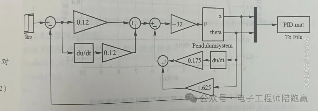
– Closed-loop Verification and Deployment: After completing the design, closed-loop desktop simulation can be performed in Simulink to verify the effectiveness of the control algorithm; then, using automatic code generation tools (such as Embedded Coder), C or HDL code can be generated for direct deployment to microcontrollers or FPGAs, achieving a seamless transition from simulation to physical implementation.
2. Industrial Automation Control: The “Technical Engine” of Smart Manufacturing In the field of industrial automation, MATLAB and Simulink, combined with artificial intelligence technology, drive the transformation of production towards intelligence: – Support for machine vision and perception technology applications: Real-time detection of product quality on production lines, achieving material sorting and robot guidance, enhancing production accuracy. – Assist in data-driven predictive maintenance: Collecting equipment operation data through the Internet of Things and big data, using machine learning to identify abnormal patterns, predicting failure risks, and reducing downtime losses. – Achieve adaptive control and optimization: Allowing industrial systems (such as thermal process control) to adjust control parameters in real-time according to environmental changes, maintaining optimal operating conditions and improving energy efficiency. 3. Signal Processing: “Full-Link Support” from Analysis to System Implementation Signal processing engineers can efficiently complete their work from signal analysis to real-time system deployment using these two tools: – A wealth of built-in functions and Apps for easy implementation of time series data analysis, preprocessing, and spectral analysis, covering scenarios such as predictive maintenance, anomaly detection, and time-frequency analysis. – Comprehensive filter design capabilities, from basic FIR and IIR filters to adaptive, multi-rate, and multi-stage designs, meeting various signal processing needs. – Modeling, simulation, and code generation capabilities: Integrating program and block diagram functionalities for signal processing system modeling and simulation, supporting fixed-point behavior modeling, and automatically generating C/C++ or HDL code for convenient deployment to embedded processors, FPGAs, and ASICs. 4. Image Processing and Computer Vision: The “Visual Hub” of Intelligent Interactive Systems When designing embedded systems with video and user interface functionalities (such as mobile phones and gaming systems), the advantages of MATLAB and Simulink are significant: – Providing a complete set of reference standard algorithms covering image processing, computer vision, and deep learning, enabling rapid design of visual solutions. – Supporting cross-tool collaboration, seamlessly integrating with teams using OpenCV, Python, and C/C++ through interoperable APIs and integration tools, breaking down tool barriers. – Simplifying algorithm acceleration and deployment: Using workflow Apps to automate common tasks, accelerating algorithm exploration; without requiring specialized programming or IT knowledge, algorithms can be accelerated on NVIDIA GPUs, cloud, and data center resources, and deployed to NVIDIA GPUs, Intel processors, FPGAs, and ARM-based embedded processors. 5. FPGA Design Simulation: Rapid Verification from Model to Hardware
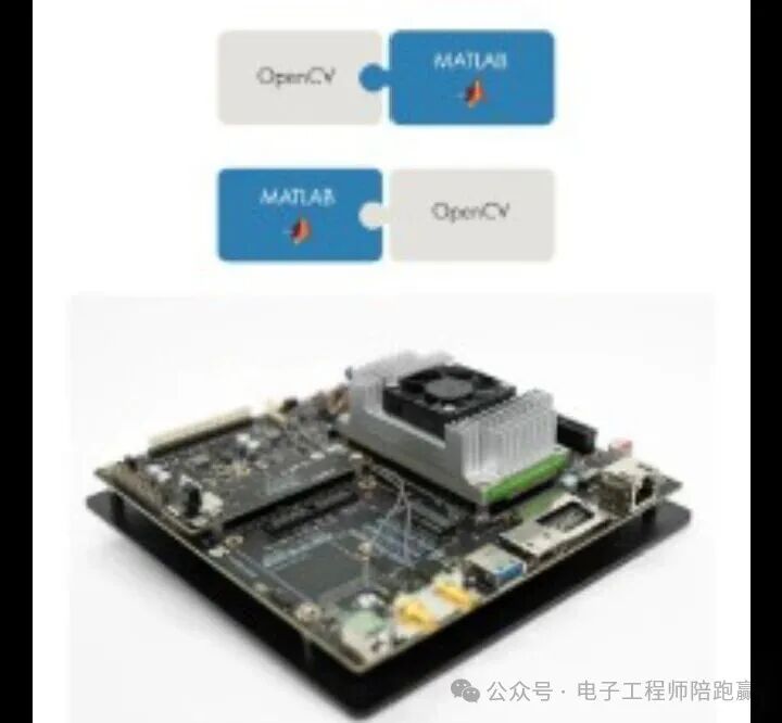
FPGA, with its programmability, has become the core carrier for rapid prototype verification and customized hardware development. MATLAB and Simulink, through model-driven design methods, significantly shorten the cycle from algorithm to hardware implementation, covering the entire process from logic design to board-level verification: – Automatic conversion from model to hardware: Using HDL Coder and Simulink HDL Workflow Advisor, Simulink models or MATLAB algorithms can be directly converted into synthesizable Verilog/VHDL code, and automatically generate test vectors (Testbench). For example, in the FPGA design of motion control for industrial robots, the position loop PID control algorithm model can be one-click converted into hardware code, saving the time cost of manually writing RTL, while improving hardware implementation efficiency through built-in code optimization rules (such as resource sharing, pipeline insertion). – Timing and resource optimization simulation: After generating HDL code, the tools can interact with FPGA development environments such as Xilinx Vivado and Intel Quartus, importing timing analysis reports (such as maximum frequency, setup/hold time margins) and resource utilization data (such as LUT, FF, BRAM, DSP slice occupancy rates). Engineers can visualize this data in MATLAB, for example, comparing resource occupancy and precision loss under different data bit-width configurations through simulation, finding the optimal balance between resource constraints and performance requirements. – Hardware-in-the-loop (HIL) simulation and real-time verification: Simulink supports establishing real-time communication links with FPGA development boards (such as Xilinx Zynq UltraScale+, Intel Stratix 10), downloading the generated bitstream files to the FPGA, and obtaining physical signals through real-time data acquisition modules (such as ADC, sensors) for closed-loop comparison with the system model in Simulink. For example, in the FPGA design of motor controllers for new energy vehicles, the FPGA can be connected to actual motor testing platforms, real-time collecting three-phase current and speed signals, comparing them with the outputs of simulation models to verify the control accuracy of hardware logic under real loads. – Collaborative simulation in heterogeneous computing scenarios: For heterogeneous computing systems composed of FPGA and CPU, GPU (such as edge AI acceleration cards), MATLAB provides a unified simulation framework to build complete models containing FPGA acceleration cores, host interfaces, and data transmission links. For example, in the design of FPGA-based image recognition acceleration systems, simulation can evaluate data interaction delays between FPGA and CPU, optimizing DMA transfer strategies to maximize the overall throughput of heterogeneous systems. 6. Chip Design Simulation: A Complete Verification System from Algorithm to Silicon In the complete process of chip design from concept to tape-out, MATLAB and Simulink build a complete simulation link from algorithm verification to hardware implementation, playing a key role especially in complex digital chips, application-specific integrated circuits (ASICs), and mixed-signal chip design: – Algorithm prototyping and functional simulation: In the early stages of chip design, engineers can build mathematical models of core algorithms (such as 5G baseband signal processing, AI inference acceleration, image compression coding, etc.) in MATLAB, verifying the functional correctness and performance limits of algorithms through numerical simulation. For example, in the design of the lidar signal processing module for autonomous driving chips, algorithms for point cloud clustering and obstacle recognition can be simulated for accuracy and latency, optimizing at the algorithm level before entering hardware design, avoiding large-scale rework later due to algorithm defects. – Architecture-level modeling and performance evaluation: Using Simulink’s modular modeling capabilities, algorithms can be decomposed into hardware-implementable functional units (such as multipliers, buffers, state machines), and register transfer level (RTL) behavioral models can be built using tools like System Generator. During simulation, data path throughput, pipeline conflicts, resource reuse rates, and other indicators can be monitored in real-time. For example, in high-performance computing chip design, simulation can evaluate the computing power density of different parallel computing architectures (such as SIMD, MIMD), providing data support for architecture selection.
– Mixed-signal simulation and interface verification: For mixed-signal circuits such as ADCs, DACs, and power management chips, Simulink achieves joint simulation of digital logic and analog circuits through co-simulation interfaces with circuit simulation tools like Cadence Virtuoso and Synopsys HSPICE. For example, in high-precision ADC chip design, the digital calibration algorithm model in Simulink can be linked with the analog front-end circuit model in HSPICE to simulate quantization errors, nonlinear distortion, and other indicators, verifying the compensation effect of digital algorithms on analog circuit defects. – Physical layer effect simulation and robustness analysis: Combining MATLAB’s statistical analysis tools, physical layer effects (such as clock jitter, power noise, signal integrity loss) introduced in chip simulation can be modeled and analyzed. For example, in high-speed SerDes chip design, simulation can evaluate eye diagram opening under different channel losses, optimizing decision feedback equalizer (DFE) parameters in conjunction with equalization algorithm models to ensure communication reliability of chips in actual physical environments. – Low-power design and verification: Using Simulink’s power analysis module, dynamic power (such as switching activity factors) and static power (such as leakage current) in chip models can be simulated in detail, and MATLAB’s optimization algorithms can automatically generate low-power strategies (such as multi-voltage domain partitioning, dynamic voltage frequency scaling). For example, in IoT chip design, simulating power distribution under different operating modes can optimize sleep-wake mechanisms, extending device battery life.
3. Why Become the “Preferred Tool” for Electronic Engineers? The widespread application of MATLAB and Simulink is primarily due to their core focus on “model-based design,” which, through visual modeling, cross-domain simulation, and automatic code generation, constructs a seamless connection from theoretical design to hardware implementation, significantly reducing the complexity and iteration costs of electronic system design. As Jeongwon Sohn, an engineer at LG Electronics, said: “Model-based design helps us easily comply with standards such as ISO 26262, especially the automatic test cases and reports in Simulink Test, significantly reducing testing workload.” Whether for full-process design of control systems, industrial automation, signal processing, image processing, or even FPGA and chip development, MATLAB and Simulink can provide electronic engineers with comprehensive support from theoretical analysis to physical deployment, making them the “all-in-one toolbox” in the field of electronic design. If you are deeply involved in electronic design, you might as well make full use of these tools to elevate your R&D efficiency to a new level!
 Previous RecommendationsCommon LCD12864 for AI Devices: A Comprehensive Guide from Hardware to ProgrammingIn-depth Understanding of TMS320F28335 Memory and Register Access: From Mapping to Practical ProgrammingPassword Lock for Program Security – In-depth Analysis of F28335 Code Security Module CSMMechanical Keyboard Input Detection Based on F28335Configuration and Application of F28335’s eQEP ModulePulse Capture – In-depth Analysis of F28335’s eCAP Module Principles and Applications
The Bridge of Digital Control and Intelligent Manipulation – Detailed Explanation of DAC Expansion and Drive
The Important Bridge of Digital Control ADC – TMS320F28335 ADC Driver and Application Program Writing Experiment
Basic Programming and Debugging of DSP28335 through Serial Port Programming
Complete Guide to Configuring and Generating DSP28335’s ePWM Program Using MATLABAnalysis of the Impact of Extreme Temperatures on Component PerformanceBuilding an Efficient and Stable Motor Control DSP Software Framework: Three-Level Interrupt Settings and Initialization of TMS320F28335Basic Experiment of ePWM Configuration of TMS320F28335Most Common Configuration Methods of 28335ePWM for Motor ControlThe God-Level Chip That Is Being Snapped Up Globally! How TI C2000 Rewrites Embedded Control History?Unveiling the Bridge Between Analog and Discrete PID Control Differential EquationsIntelligent Self-Tuning Method for PID ParametersThoroughly Understanding the Structure, Differences, Conversion, and Application of “Series” and “Parallel” PIDTrend Curve for Thoroughly Tuning PID ParametersKey Components of Robots (6) – Stepper MotorsKey Components of Robots (4) – DC Torque MotorsField Effect Transistor Series (9) – The Continuation of H-Bridge Circuit and Drive