Enhancing anti-interference is one reason.
Standard UART can choose 16x sampling or 64x sampling; I personally think it should be for convenient frequency division design.
The RXD front end of the standard UART has a “1 to 0 transition detector.” When it continuously receives 8 ground level signals on RXD, the detector considers that the RXD line has a start bit and enters the receiving data state. In the receiving state, the receiving controller samples data bits 7, 8, and 9 and follows the principle of majority voting to determine the final value. The fundamental purpose of this method is still to enhance anti-interference and improve the reliability of data transmission. The sampling signal is always at the midpoint of each received bit, which can avoid edge distortion at both ends of the data bits and prevent errors caused by the non-completely synchronized receiving and sending clock frequencies.
First, let’s review the data format of asynchronous serial communication:

Since the transmission line is in a logic “1” state during idle status, and data transmission always starts with a start bit “0,” when the receiver detects a transition from “1” to “0,” it considers it a possible start bit (interference-induced transitions need to be excluded); once the start bit is confirmed, the receiver knows the transmitter has started sending, and it can receive subsequent data according to this data communication format; when a stop bit “1” is detected, it indicates that a frame of character data has been completely sent.
The most important aspect of receiver design is how to improve the accuracy of sampling, ideally ensuring that the sampling point is at the midpoint of the sampled data’s time. Therefore, when receiving samples, a clock with a rate n times (n≥1) higher than the data baud rate must be used to sample the data. In this program, a 16x baud rate clock is used for sampling. Combining the illustrations, let’s explain how to ensure that the sampling moment is at the midpoint of the sampled data’s time:
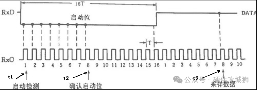
1. If a low level is detected at time t1, start continuous detection of this low level.
2. After detecting 8 clock cycles, reaching t2, if the previous 8 cycles are all low levels, it is considered that the start pulse has been detected. Otherwise, it is considered interference, and detection is restarted.
3. After detecting the start bit, count 16 sampling clock cycles to reach the midpoint of the first data bit’s time t3, sample data at this moment, and save it.
4. Then, after another 16 cycles, it reaches the midpoint of the second data bit’s time; sampling occurs at this moment. Then, after another 16 cycles, it reaches the midpoint of the third data bit’s time, sampling occurs at this moment… and continue this way until all data bits are sampled.
——The End——

Click👇 to Follow

Animated GIFs to Understand Common Communication Protocols, Save!
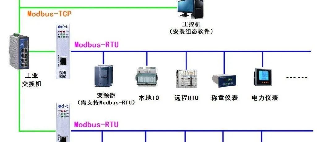
Detailed Explanation of the Modbus Communication Protocol
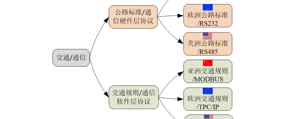
Easy to Understand Communication Protocols at Software and Hardware Levels