Big Cat says:
Translation compilation of Chapter 11 from the book RFSoC-Book, detailed introduction of this book can be found in the first article of this series.
“An open-source masterpiece, ‘Software Defined Radio Based on Zynq UltraScale+ RFSoC'”
Mr. Big Cat, WeChat public account: Mr. Big Cat’s Little Bookshelf, an open-source masterpiece, ‘Software Defined Radio Based on Zynq UltraScale+ RFSoC’
Digital Complex Mixer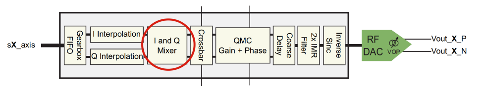 Functionally, the complex mixer in the RF-DAC is the same as the complex mixer in the RF-ADC; the difference is that its role in the RF-DAC is to modulate data rather than demodulate data. The function of the mixer is to shift the signal to the target frequency band by mixing the input signal with a higher frequency carrier. The RF-DAC mixer includes a 48-bit digital NCO fine mixer that supports modulation with carriers of any frequency, and a coarse mixer for mixing with one of a set of preset carriers. The mixer supports I/Q to real and I/Q to I/Q modes. Figure 11.19 shows the block diagram of the mixer.Coarse Mixer and Bypass ModeThe coarse mixer is the simpler of the two mixing modes, allowing mixing only with a limited set of carriers, namely: fs/2, fs/4 or –fs/4. However, the power consumption of the coarse mixer is much lower than that of the fine mixer due to its simpler architecture, particularly as it does not involve storing and accessing a large sine wave amplitude lookup table.
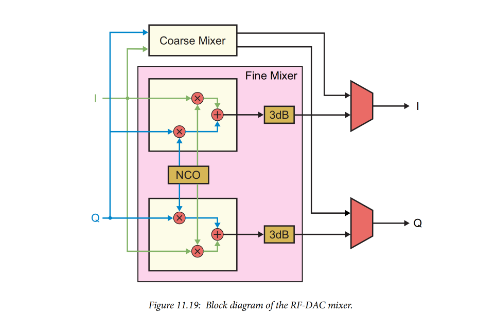 The coarse mixer can also be used to bypass the entire mixing component, in which case the signal simply passes through the mixer without modulation. In this mode, only real input and output signals are allowed.Fine MixerThe fine mixer consists of a numerically controlled oscillator (NCO) and a set of modulators (multipliers and add/subtract operators), capable of offsetting the baseband signal at any frequency, including phase control. The NCO provides fine control over the generated frequency in addition to 18-bit phase adjustment, both of which can be programmed by the user. If multi-tile synchronization is used, the phase of the NCO can also be synchronized between tiles.As shown in Figure 11.19, the output of the fine mixer includes a 3dB attenuation block, which helps to avoid potential overflow during mixing (functionally, the attenuation block multiplies the output signal amplitude by 0.707, corresponding to halving the signal power, i.e., 3dB attenuation). The attenuation block can be turned on or off as needed.After mixing, signals in the even Nyquist zones are inverted (flipped left and right in frequency), while signals in the odd Nyquist zones are not. Any inversion can be corrected by using negative frequencies in the NCO.Due to the additional 2x interpolation introduced by the image rejection (IMR) filter in third-generation (Gen 3) devices, the sampling rate at the mixer is equal to half the DAC output sampling rate (when IMR is enabled). Next, we will discuss the IMR filter in more detail.Image Rejection (IMR) Filter
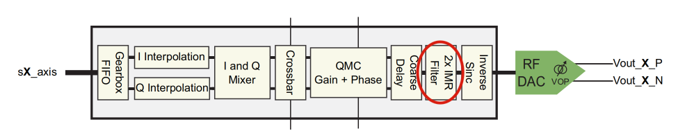 The IMR filter is only available in third-generation and DFE devices, and it can eliminate unwanted spectral images after mixing occurs. The IMR filter can provide low-pass filtering, preserving signals in the first Nyquist zone while attenuating signal images in the second Nyquist zone; or provide high-pass filtering, attenuating signals in the first Nyquist zone while preserving signal images in the second Nyquist zone.In addition to filtering, IMR also introduces 2x interpolation for the signal. Therefore, the maximum interpolation rate of the RF-DAC increases from 40x to 80x. If IMR is enabled and only 2x interpolation is needed, the interpolation chain before the mixer is bypassed, using only the IMR interpolator. The 2x interpolation introduced by the IMR filter has implications for system design, as the sampling rate at the mixer output will be half of the RF-DAC output sampling rate. This issue will be discussed in more detail in subsequent articles.In the RF-DAC data pipeline, the IMR filter is located after the DUC and QMC, but before the inverse sinc filter. While users can enable and disable IMR at runtime, it can only be used when the DUC is enabled, meaning that IMR cannot be used when the DUC is in bypass mode. Figure 11.20 shows the RF-DAC data path with various routing options for the IMR filter.
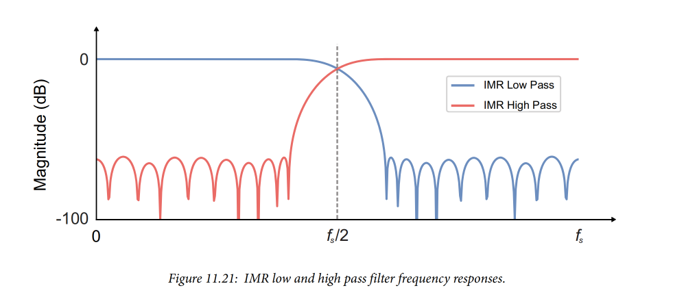
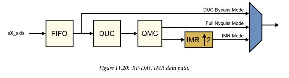 The high-pass and low-pass filters of the IMR filter are symmetrical, both providing a stopband attenuation of 60dB relative to the carrier (60dBc). It is important to note that the cutoff frequency of the Nyquist filter is relative to the sampling rate before interpolation, meaning that the cutoff frequency is related to the sampling rate at the output of the digital upconverter (DUC), not the sampling rate at the IMR output.For example, suppose the sampling rates after the DUC and IMR are 1 Gsps and 2 Gsps, respectively. In this case, the cutoff frequency of the IMR filter would be 500 MHz, not 1 GHz. Figure 11.21 shows the frequency response of the two IMR filters.