Cover Image On July 21, 2020, SpaceX’s Falcon 9 Heavy rocket is about to launch. The NEOWISE comet is right above it, traversing the vast universe. Many websites have selected this photo as the annual photo of space exploration.[Previous Highlights]: Beginner’s Guide: Practical Guide to Adjusting GPU on RK Platform Ubuntu
Welcome to follow “Embedded Sharing“, updated weekly! ☞
Main ContentThis collection shares my original notes when I first started debugging embedded BSP, the first board I debugged in my debugging journey. The content is suitable for beginners to quickly get started with debugging; experts, please be gentle~
Before Debugging
1. What is the CAN Bus?
The Controller Area Network (CAN) is a serial communication protocol bus used for real-time applications, which can transmit signals using twisted pair cables, and is one of the most widely used field buses in the world.
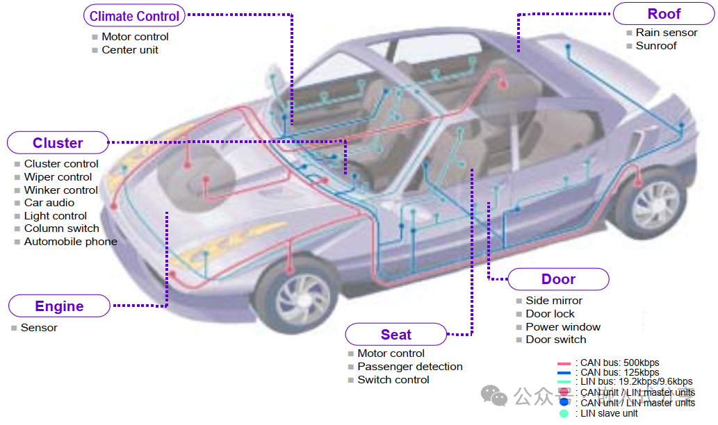
The CAN protocol is used for communication between various components in automobiles, replacing expensive and bulky wiring harnesses. The robustness of the protocol extends its use to other automation and industrial applications. Features of the CAN protocol include integrity in serial data communication, real-time support, transmission rates of up to 1Mb/s, and 11-bit addressing with error detection capabilities.
2. What are the characteristics of CAN?
-
Multi-master Control
When the bus is idle, all nodes can start sending messages (multi-master control). The first node to access the bus gains the right to send (CSMA/CA method), and if multiple nodes start sending simultaneously, the node sending the higher priority message gains the right to send.
-
Message Transmission
In the CAN protocol, all messages are sent in a fixed format. When the bus is idle, all nodes connected to the bus can start sending new messages. When two or more nodes start sending messages simultaneously, priority is determined based on the identifier (referred to as ID). The ID does not represent the destination address of the message but indicates the priority of the message accessing the bus.When two or more nodes start sending messages simultaneously, each bit of the message ID is compared for arbitration. The node that wins arbitration (determined to have the highest priority) can continue sending the message, while the node that loses arbitration immediately stops sending and begins receiving.
-
System Flexibility
Nodes connected to the bus do not have information similar to an “address.” Therefore, when adding nodes to the bus, the hardware and application layers of other nodes connected to the bus do not need to change.
-
Communication Speed
The appropriate communication speed can be set according to the scale of the entire network.
All nodes in the same network must be set to a uniform communication speed. If even one node has a different communication speed, that node will output error signals, disrupting communication across the entire network. Different networks can have different communication speeds.
-
Remote Data Request
Data can be requested from other nodes by sending a “remote frame.”
-
Error Detection, Notification, and Recovery Functions
All nodes can detect errors (error detection function). The node that detects an error will immediately notify all other nodes (error notification function).
If a node that is sending a message detects an error, it will forcibly terminate the current transmission. The node that forcibly ends the transmission will repeatedly attempt to resend the message until it is successfully sent (error recovery function).
-
Fault Isolation
CAN can determine whether the type of error is a temporary data error on the bus (such as external noise) or a persistent data error (such as internal faults, driver faults, disconnections, etc.). With this function, when a persistent data error occurs on the bus, the node causing the fault can be isolated from the bus.
-
Connections
The CAN bus can connect multiple nodes simultaneously. The theoretical limit on the number of connectable nodes is unlimited. However, in practice, the number of connectable nodes is limited by the time delay and electrical load on the bus.Reducing the communication speed increases the number of connectable nodes; increasing the communication speed decreases the number of connectable nodes.
3. Why is the CAN bus needed?
Traditional “point-to-point” communication (e.g., device A directly connected to device B) has two major pain points:
First, as the number of devices increases, the complexity of wiring rises exponentially (e.g., a car has hundreds of ECUs, requiring thousands of wires for point-to-point connections);Second, there is a lack of fault tolerance; a broken wire can cause the corresponding device to fail.
The essence of the CAN bus ismulti-master nodes sharing a single bus: All devices (such as the engine ECU, brake ECU, dashboard in a car) are connected via “two differential signal lines” (CAN_H, CAN_L), enabling “one wire for multiple device communication,” while addressing issues of “interference resistance,” “fault tolerance,” and “priority scheduling.”
Today, the CAN protocol is mainly used for communication between various components in automobiles, replacing expensive and bulky wiring harnesses. Its robustness also makes it suitable for automation and industrial environments.
4. What components make up a CAN node?
A CAN node typically consists of: a CAN transceiver, a CAN controller, and terminal communication devices.
The CAN bus transmits data via differential signals; the CAN transceiver converts differential signals to TTL level signals or vice versa; the CAN controller receives TTL level signals and transmits them to the CPU.
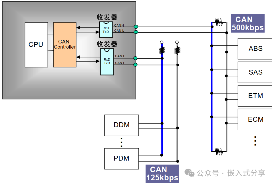
Common SoCs like Allwinner and RK already integrate CAN controllers internally, allowing for reading and sending CAN message data through configuration.
5. How is the signal transmitted on the CAN bus?
On the CAN bus, the potential difference between CAN_H and CAN_L represents the CAN signal. The potential difference on the CAN bus is divided into dominant voltage (logical 0) and recessive voltage (logical 1).
To understand how signals are transmitted on the CAN bus, one must understand thebus topology anddifferential signals.
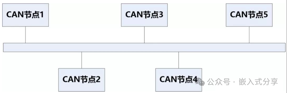
Bus Topology: A linear topology is recommended.
Core Medium:CAN_H (high-level line) andCAN_L (low-level line), using “differential signal transmission” (key to electromagnetic interference resistance).Node Connection: All devices (nodes) connect their CAN_H and CAN_L in parallel to the bus, requiring no complex wiring.Terminal Matching: A “120Ω terminal resistor” must be connected at both ends of the bus to absorb signal reflections (to avoid distortion caused by signal overlap).
Although the CAN bus can support various network topologies, in practice, alinear topology is predominantly used, and the ISO 11898-2 high-speed CAN physical layer specification also recommends a linear topology.
Differential Signals: The Core Design for Interference Resistance
Traditional single-ended signals (like UART’s TX/RX) transmit via the voltage difference between “signal line and ground,” making them susceptible to external electromagnetic interference. The CAN bus’s differential signals transmit throughthe voltage difference between CAN_H and CAN_L, with the following rules:
Recessive Signal (1): CAN_H ≈ 2.5V, CAN_L ≈ 2.5V, differential voltage (CAN_H – CAN_L) ≈ 0V;Dominant Signal (0): CAN_H ≈ 3.5V, CAN_L ≈ 1.5V, differential voltage ≈ 2V;Interference Cancellation: External interference affects both CAN_H and CAN_L simultaneously, keeping their voltage difference relatively unchanged, thus effectively resisting electromagnetic interference (EMI).Hardware Design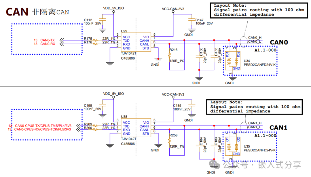
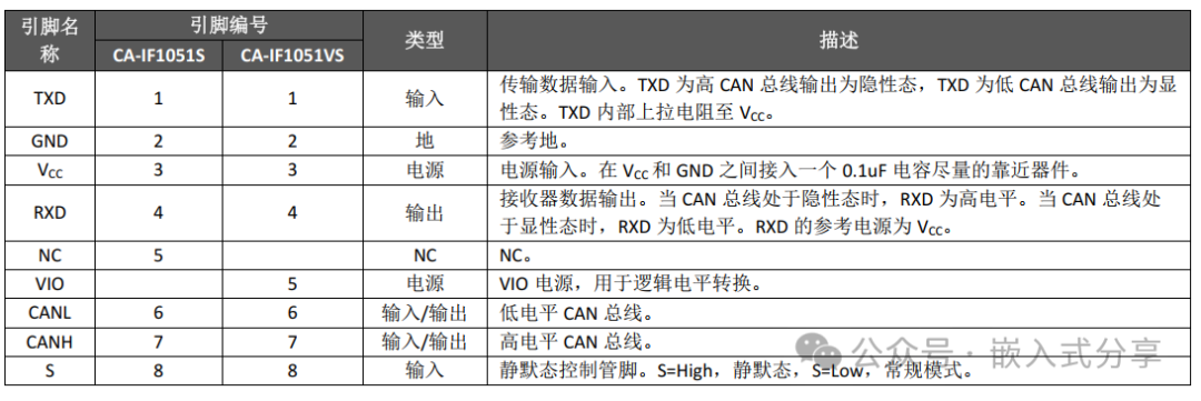
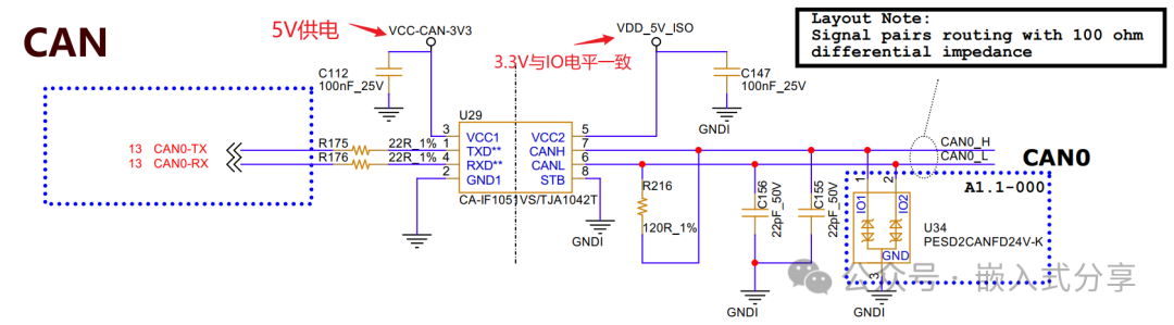
The pin definitions for the transceiver are as follows:
Software Configuration
Allwinner’s CAN is called AWLINK.
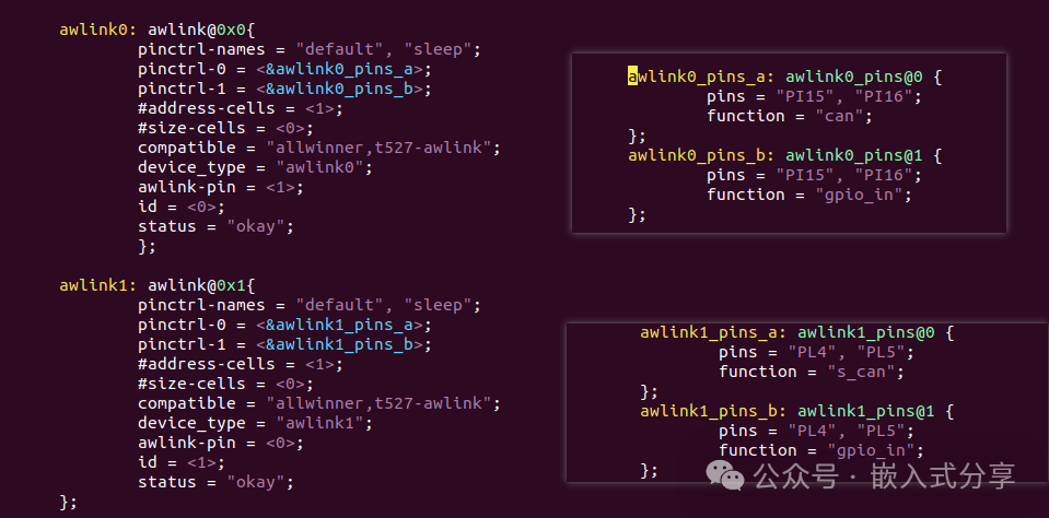
Driver Path: bsp/drivers/awlink/sunxi_awlink.cDTS Configuration
Kernel Configuration
CONFIG_CAN=y
CONFIG_AW_AWLINK_SUN55I=y
CONFIG_BR2_PACKAGE_IPROUTE2=y
Debugging Process
Problem 1: CAN pins are not being driven or called
[Problem Description]: After loading the driver, it was found that the CAN pins were not being driven or called, as shown in the log below.
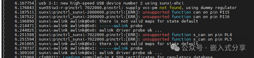
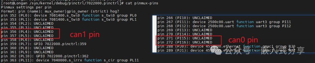
[Problem Analysis]: The issue with the T527 CAN pins shows that the CAN node has appeared and can be normally down/up, but data cannot be transmitted. It seems that the driver has not called the specific CAN pins, initially suspecting incorrect pin configuration.
However, upon checking, it was found that the issue was not due to incorrect pin configuration, and feedback was communicated with the original factory FAE.
[Problem Solution]: The original factory SDK lacks support for CAN functionality, requiring a patch.
Problem 2: CAN cannot communicate
[Problem Description]: After applying the patch, the CAN pins were correctly driven, but communication was still not possible.

[Problem Analysis]: The driver loading, pin calling, and CAN node are all normal, indicating that there are likely no issues on the software side. Next, hardware should be the focus of investigation. Reading the CAN transceiver data sheet, check the circuit and various voltages.
[Problem Solution]: The voltage levels on both ends of the CAN transceiver were mismatched; resolving this issue allowed for normal CAN communication.
Function Verification
Check CAN Information
(1) Use the command ifconfig awlink0 to check if the AWLINK driver is loaded correctly; the following printout indicates that the AWLINK driver has loaded successfully.
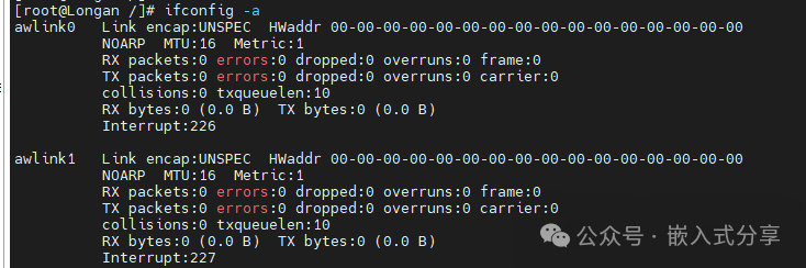
(2) Execute ip -d -s -s link show awlink0 command to view the configuration information of awlink0, including baud rate, bit timing settings, etc. Check if the AWLINK testing tools (ip, cangen, candump, etc.) can be used normally.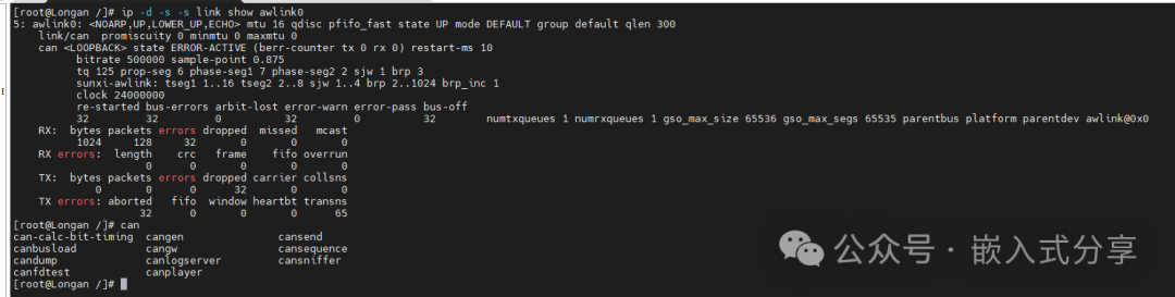
Transmitting and Receiving Data (Integration Testing)
Connect CAN0_L to CAN1_L and CAN0_H to CAN1_H.
ip link set awlink0 down
ip link set awlink0 type can bitrate 500000
ip link set awlink0 up
ip link set awlink1 down
ip link set awlink1 type can bitrate 500000
ip link set awlink1 up
awlink0 sends, awlink1 receives
candump -ta awlink1 & cansend awlink0 123#01.02.03.04.05.06
killall candump
awlink1 sends, awlink0 receives
candump -ta awlink0 & cansend awlink1 123#01.02.03.04.05.06
killall candump
Debugging Summary
From the perspective of BSP debugging, the debugging approach for CAN is not much different from that of UART; configuring two wires is sufficient. This is because many link layer-related protocols and communication mechanisms have been encapsulated. For example, the driver encapsulates the software implementation, and the SoC’s CAN controller and CAN transceiver encapsulate the hardware implementation.
However, we must understand the basic working principles of CAN and hardware circuit design to analyze and locate issues promptly when they arise. Otherwise, we will truly become DTS engineers.
Next time, we will share about HDMI debugging, stay tuned @
(End)