ProfiNet Embedded Board: A mainstream alternative for implementing ProfiNet industrial Ethernet applications
·Industry/Scenario: Multi-axis servo drive control on packaging lines
·Device/Board: StableLink Technology’s “EthernetIP to SPI” embedded board, serving as the control interface for servo drives
·PLC: Siemens S7-1500 (Profinet IO Controller)
·Network Topology: Siemens PLC communicates with gateway/bridge devices via Profinet, which maps Profinet data to EtherNet/IP, and then exchanges commands and status with the MCU/SPI side servo controller through StableLink’s EthernetIP to SPI board
1 Hardware Installation:
As shown in Figure 1, install the WL-EIP-SPI core board onto the baseboard
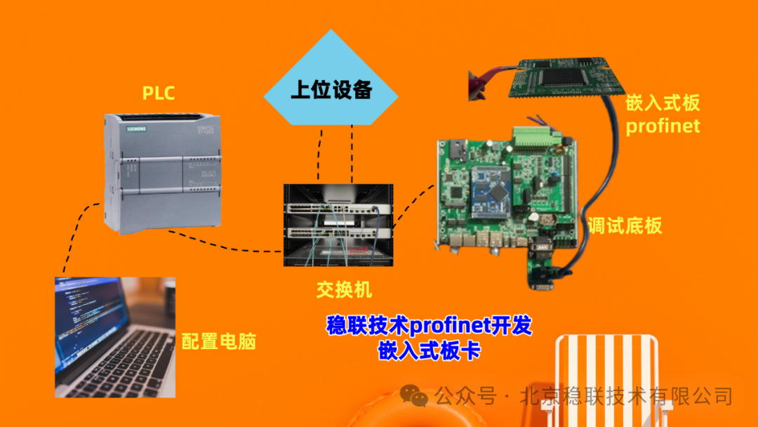
As shown in Figure 2, connect the programming computer, switch, configuration PC, and board system.
2 PC Configuration and PLC Setup
2.1 Install Device GSD in the Configuration Software
Unzip the GSD compressed file and place it in any directory, which should contain the following three files
Open the configuration software, and in the menu bar, go to “Options -> Manage General Station Description Files” to access GSD management.
Select the unzipped path of the first GSD file, check the file, and install it.
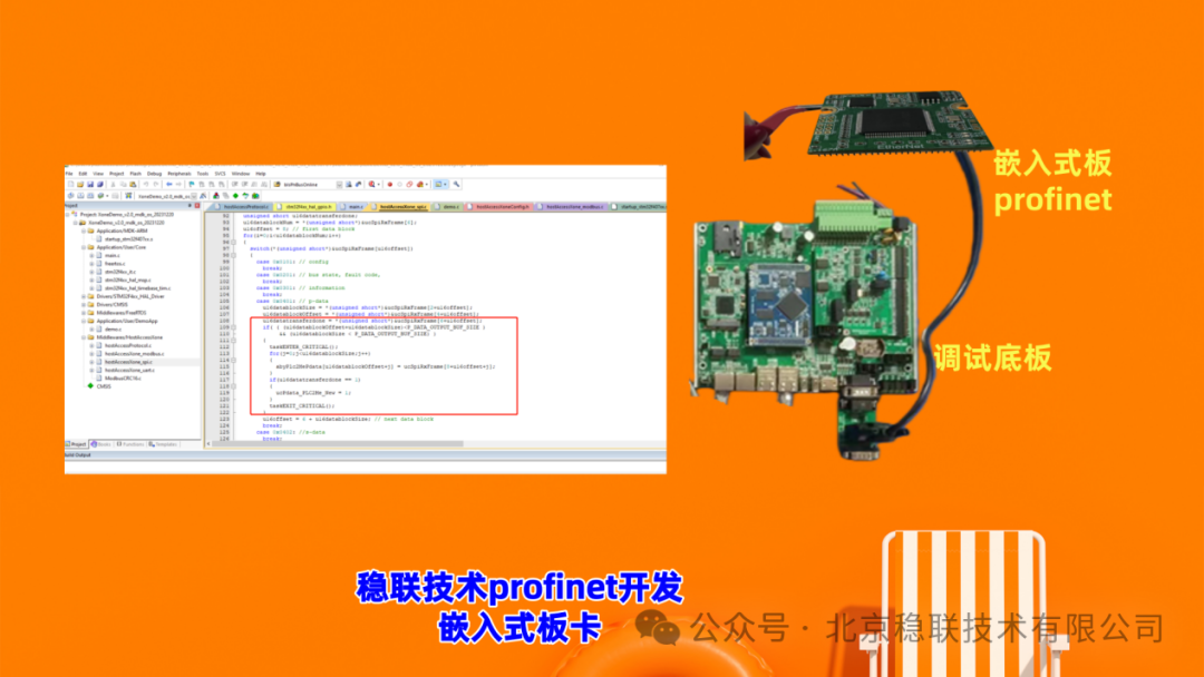
Key Points of Operation
·The PLC sends motion commands to the board (connecting to the EtherNet/IP side of the StableLink board) via Profinet
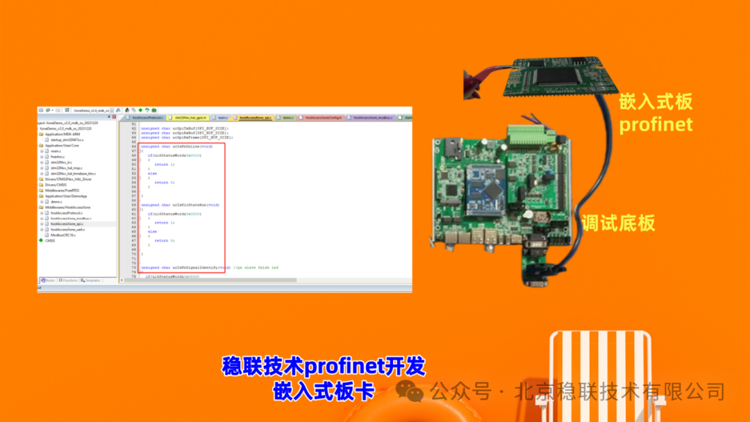
·The StableLink’s EtherNetIP to SPI board transmits the received commands to the servo drive’s MCU via SPI, which executes motion control based on the instructions
·The servo drive returns encoder feedback, temperature, overload, and other status to the board via SPI, which then sends the data back to the gateway via EtherNet/IP, and the gateway maps the data back to Profinet for the PLC
·
·Example of Data Mapping (Simplified for Understanding):
§Number of Axes: 2 Axes
§Output Data (Target Values)
§TargetPos_A, TargetPos_B (each 32 bits, unit in servo encoder counts)
§TargetVel_A, TargetVel_B (if needed, 32 bits, unit in counts/second)
§Input Data (Feedback/Status)
§ActualPos_A, ActualPos_B (each 32 bits)
§StatusWord_A, StatusWord_B (each 16 bits, indicating readiness, motion, error, etc.)
oEtherNet/IP Side (StableLink board’s SPI mapping to MCU):
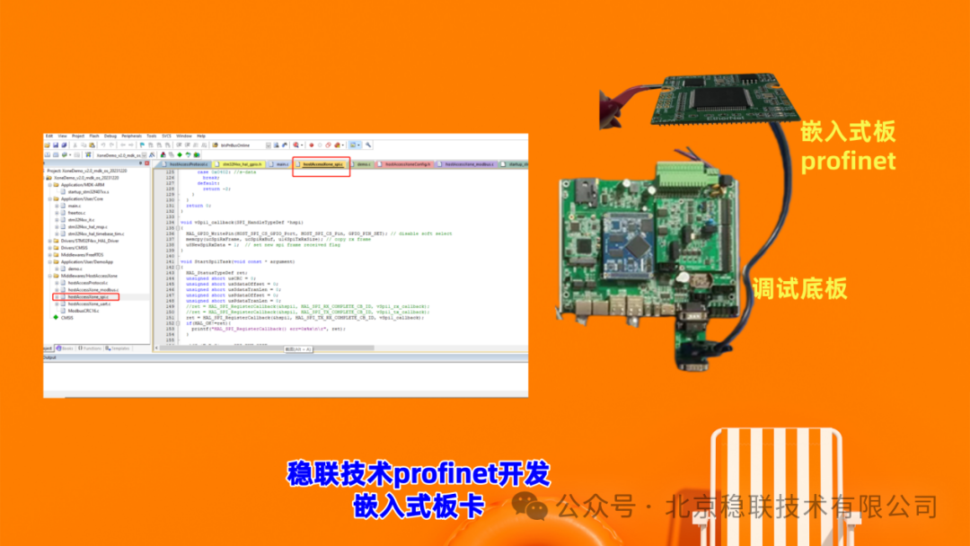
§Reference Registers: CmdRegister[0..3] correspond to low/high segments of TargetPos_A/TargetPos_B, CmdRegister[4..7] correspond to TargetVel (if any)
§Feedback Registers: FeedbackRegister[0..3] correspond to low/high segments of ActualPos_A/ActualPos_B, FeedbackRegister[4..5] correspond to status
§
oSPI Side (Servo Controller MCU):
§Parse CmdRegister to convert target values into motion commands for the servo drive
§Write back the MCU’s ActualPos, temperature, and other feedback to FeedbackRegister, which is reported by the board to the EtherNet/IP network, ultimately returning to the PLC