
With the development of microcontrollers, their applications in household appliances, industrial automation, production process control, and smart instruments are becoming increasingly widespread. However, various electrical devices within the same power system are closely interconnected through electrical or magnetic links, influencing each other. Electromagnetic oscillations caused by changes in operating modes, faults, or switching operations can affect many electrical devices.
This poses a significant threat to the reliability and safety of our microcontroller systems. Microcontroller measurement and control systems must operate stably and reliably over long periods; otherwise, control errors may increase, and in severe cases, the system may fail, leading to substantial losses. Therefore, the issue of interference resistance in microcontrollers has become a problem that cannot be ignored.
1. The Impact of Interference on Microcontroller Application Systems
01 Increased Measurement Data Errors
Interference can invade the input channels of the analog signals in the microcontroller system’s measurement unit, superimposing on the measurement signals and increasing data acquisition errors. This is particularly problematic when detecting weak signals, where interference can even drown out the measurement signals.
02 Control System Failure
The control signals output by the microcontroller typically depend on the status input signals of certain conditions and the logical processing results of these signals. If these input status signals are interfered with, introducing false status information, it will lead to increased output control errors or even control failures.
03 Impact on Microcontroller RAM Memory
In a microcontroller system, programs and tables, as well as data, are stored in program memory such as EPROM or FLASH, which prevents these data from being damaged by interference. However, data in on-chip RAM, external RAM, and E2PROM can still be affected by external interference.
04 Abnormal Program Operation
External interference can sometimes cause the machine to reset frequently, affecting the normal operation of the program. If external interference alters the value of the microcontroller’s program counter (PC), it disrupts the normal operation of the program.
Due to the random nature of the PC value after interference, the program will execute a series of meaningless instructions, eventually entering a “dead loop,” which can lead to severe output confusion or system crashes.
2. How to Improve Equipment’s Interference Resistance
Addressing Interference from the Power Supply
Each unit in a microcontroller system requires a DC power supply, which is generally generated from the AC mains through transformation, rectification, filtering, and voltage regulation. Therefore, various interferences on the power supply can introduce noise into the system.
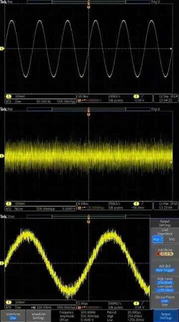
Moreover, due to the shared AC power supply, mutual interference can occur between electronic devices through the power supply, making it especially important to suppress power supply interference. The main types of power supply interference include:
01 High-Frequency Interference in Power Lines
Power supply lines act as receiving antennas, capable of coupling high-frequency interference signals from lightning, electric arcs, and radio stations through the primary of the power transformer to the secondary, forming interference to the microcontroller system.
To resolve this type of interference, interface protection is generally implemented; filters can be added at the interface, or isolated power supply modules can be used.
02 Transient Noise from Inductive Loads
Disconnecting large inductive loads can generate significant current and voltage rate changes, resulting in transient noise interference, which is a major form of electromagnetic interference.
To mitigate this interference, shielding wires and twisted pair cables can be used, or filtering can be applied at the power and signal interfaces.
Both methods require good grounding of the system; filters and interface filtering circuits must be well grounded to effectively dissipate interference.
3. Anti-Interference Techniques for Analog Signal Sampling
Microcontroller application systems typically need to sample one or more analog signals and convert them into digital signals for processing via A/D conversion.
To improve measurement accuracy and stability:
- Ensure the conversion accuracy of the sensor itself;
- Stabilize the power supply for the sensor;
-
Stabilize the measurement amplifier;
- Stabilize the reference voltage for A/D conversion;
- Prevent external electromagnetic induction noise;
If not handled properly, weak useful signals may be completely drowned out by useless noise signals.
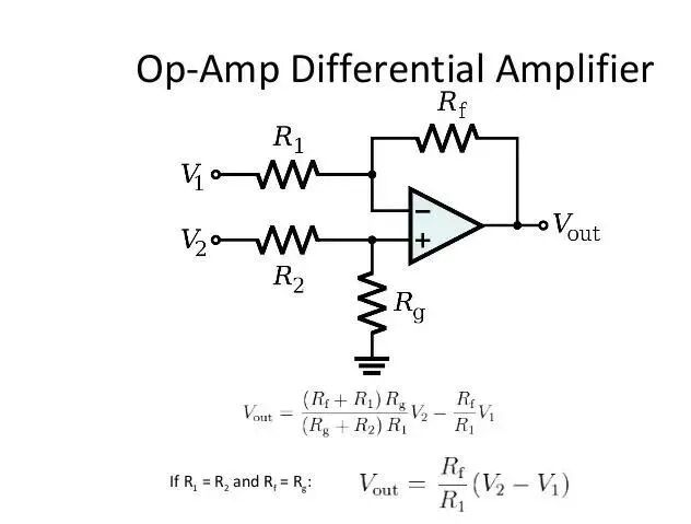
In practical work, differential input measurement amplifiers can be used, along with shielded twisted pair cables for signal transmission, or converting voltage signals to current signals, and employing RC filtering techniques.
 4. Anti-Interference Techniques for Digital Signal Transmission Channels
Digital output signals can serve as driving signals for controlled devices in the system (e.g., relays), while digital input signals can act as response and instruction signals for devices (e.g., limit switches, start buttons).
The digital signal interface is one of the main channels through which external interference enters the microcontroller system.
In engineering design, anti-interference measures for the input/output processes of digital signals include:
- Shielding techniques for transmission lines, such as using shielded cables and twisted pair cables;
- Implementing signal isolation measures;
-
Proper grounding; since digital signals form common impedance interference during level conversion, selecting appropriate grounding points can effectively suppress ground noise.
5. Hardware Monitoring Circuits
In microcontroller systems, to ensure reliable and stable operation and enhance interference resistance, hardware monitoring circuits need to be configured. The functions of hardware monitoring circuits include:
- Power-on reset: ensuring the system starts correctly when powered on;
-
Power failure reset: generating a reset signal to the system when the power supply fails or the voltage drops below a certain level;
- Hardware watchdog: resetting the system when the processor encounters interference or program chaos leading to a “deadlock”.
6. Reasonable PCB Circuit Layout
The quality of PCB design significantly impacts interference resistance. Therefore, when designing PCBs, general PCB design principles must be followed, and anti-interference design requirements should be met. The following two points are emphasized:
01 Placement of Key Components
In component layout, similar to other logic circuits, related components should be placed as close as possible to achieve better noise immunity.
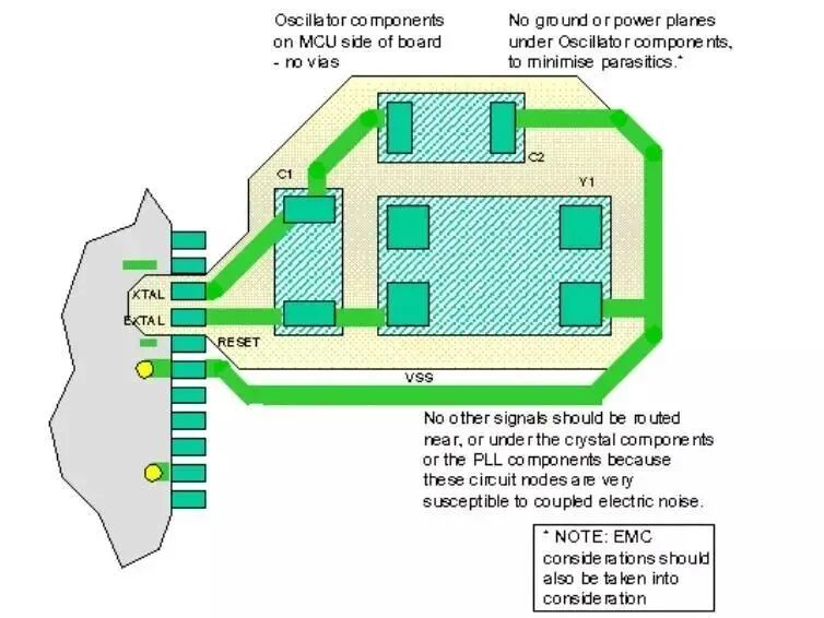
- Clock generators, crystal oscillators, and the CPU’s clock input pins are prone to noise and should be placed close to each other;
-
The CPU reset circuit and hardware watchdog circuit should be as close as possible to the corresponding CPU pins;
- Components that generate noise and high current circuits should be kept as far away from logic circuits as possible.
02 Correct Grounding of D/A and A/D Conversion Circuits
D/A and A/D chips, as well as sampling chips, provide separate digital and analog grounds, each with corresponding pins.
In circuit design, all components’ digital and analog grounds must be connected separately, with the digital and analog grounds connected at only one point. Additionally, shielding can be used to isolate spatial radiation.
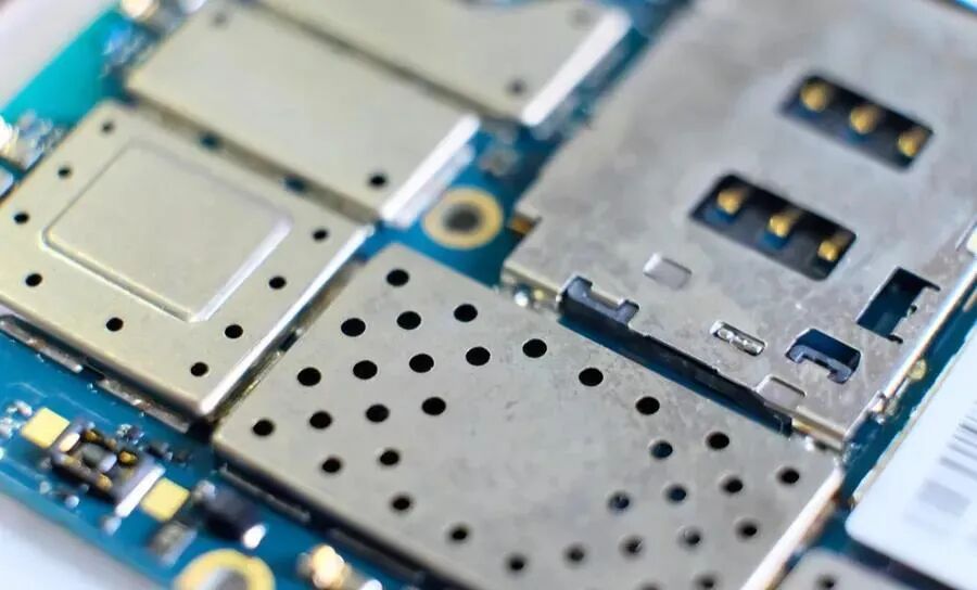
For components with particularly high noise (e.g., variable frequency power supplies, switch-mode power supplies), metal enclosures can be used to reduce noise interference to the microcontroller. For parts that are easily affected by interference, shielding covers can be added and grounded to short-circuit the interference signals to ground.
 7. Software Anti-Interference Principles and Methods
Although we have implemented hardware anti-interference measures, the causes of interference signals are complex and highly random, making it difficult to ensure that the system is completely free from interference.
Therefore, software anti-interference techniques are often employed as a supplement to hardware measures. Software anti-interference methods are characterized by simplicity, flexibility, and low cost, making them widely used in systems.
01 Digital Filtering Methods
Digital filtering is the process of extracting the most accurate data based on multiple samples of an analog signal through software algorithms. The algorithms for digital filtering are flexible, allowing for parameter selection, and their effectiveness often surpasses that of hardware filtering circuits.
02 Input Signal Redundancy Detection Methods
Input signal interference is a series of discrete spikes superimposed on valid level signals, lasting for a very short time.
When the control system experiences input interference that cannot be effectively suppressed by hardware, software redundancy detection methods can be used to achieve the goal of “removing the false and retaining the true,” considering a result valid only when two or more consecutive readings are identical.
If the signal continues to fluctuate, an alarm signal can be issued when the maximum count limit is reached. This input method can be applied to signals from various types of switch sensors, such as limit switches, travel switches, and operation buttons.
Inserting delays between consecutive data acquisitions can help deal with wider interference.
03 Output Port Data Refresh Methods
Software anti-interference design for switch outputs mainly involves redundancy in output, which is an effective measure to enhance the anti-interference performance of output interfaces. This is particularly necessary for control signals output via latches.
By repeatedly outputting data within the shortest possible cycle, the affected devices will receive correct information before they can respond to erroneous signals, thus preventing misoperations. In terms of program structure, a data buffer can be established for output data, which is output within the program’s periodic loop.
For incremental control devices, this method cannot be used; instead, data transmission correctness must be determined through feedback information from the device. When executing the redundancy output function, for programmable interface chips, the working mode control word and output status word should be set repeatedly to ensure reliable operation of the output module.
04 Software Interception Techniques
When interference enters the microcontroller system at the CPU level, the consequences can be severe, potentially causing system failure.
The most typical failure is the corruption of the program counter (PC) state, leading the program to jump from one area to another, or causing the program to “fly around” within the address space, or to enter a “dead loop.”
Using software interception techniques can intercept “flying” programs or help the program escape from a “dead loop,” bringing the running program back on track to a designated entry point.
05 “Software Watchdog” Technology
When the PC is interfered with and loses control, causing the program to “fly around,” it may also lead to the program entering a “dead loop.” When software interception techniques cannot help the uncontrolled program escape the “dead loop,” program monitoring technology (WDT TIMER), also known as watchdog technology, is typically employed to free the program from the “dead loop.”
The WDT is a combination of software and hardware measures against program runaway, with its hardware component being a timer or monostable circuit that operates independently. Its timing output is connected to the CPU’s reset line, while its timing reset is controlled by the CPU.
Under normal circumstances, after starting the WDT, the CPU periodically resets it, preventing timing overflow, which is akin to being in sleep mode and having no effect. In abnormal situations where the CPU’s timing logic is disrupted and program execution is chaotic, it cannot periodically reset the WDT. When the WDT’s timing overflows, its output resets the system, preventing the CPU from becoming paralyzed due to temporary interference.
8. Conclusion
With the widespread application of microcontroller systems and advancements in technology, the issue of electromagnetic interference is becoming increasingly prominent. Promoting existing mature anti-interference technologies and researching new technologies and directions for interference resistance is an urgent task in microcontroller application technology. In the design and application of microcontroller systems, as long as the electromagnetic compatibility of the equipment is fully considered and various technical measures are implemented to eliminate interference, the stability and reliability of the equipment can be significantly improved.


Collection of Electronic Books from the Resource Compilation

[Complete Set of Hardware Learning Materials Collection]