With years of experience, I often work with Hall current sensors. They are commonly used in scenarios such as variable frequency speed control, UPS power supplies, and power grid monitoring. They can measure both AC and DC, isolate high voltage, and their accuracy and response speed far exceed traditional current transformers and shunts. Today, I will share a comprehensive guide on Hall current sensors from principles to applications based on my practical experience.
01
Understanding the Core: The Working Principle of Hall Current Sensors
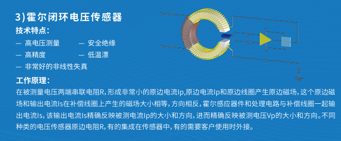
The core of Hall current sensors is “the Hall Effect + magnetic coupling“, which can be simply described as “using a magnetic field to transmit signals for electrically isolated measurements“. Taking the commonly used zero magnetic flux closed-loop type as an example:
1. When the primary current (the current being measured Ip) flows through the wire, it generates magnetic field lines, which are concentrated around the air gap by the magnetic ring;
2. The Hall element in the air gap will induce a few millivolts of weak voltage, which is proportional to the strength of the primary magnetic field;
3. The subsequent amplification circuit converts the weak voltage into the secondary current Is, ultimately satisfying the relationship:Ip×Np = Is×Ns (Np is the number of turns in the primary coil, Ns is the number of turns in the secondary coil, usually Np=1);
4. The secondary current passes through the measurement resistor RM, which outputs a voltage signal proportional to the primary current, facilitating subsequent data collection.
Key Supplement: The sensor’s supply voltage must be within the specified range. The minimum voltage for single-phase powered sensors is twice that of two-phase powered sensors, and the measurement range will also be higher; the measurement range Imax is usually slightly higher than the rated value, leaving a margin to handle overloads.
02
Common Models, Structures, and Installation Wiring Techniques
1. Introduction to Two Typical Sensors
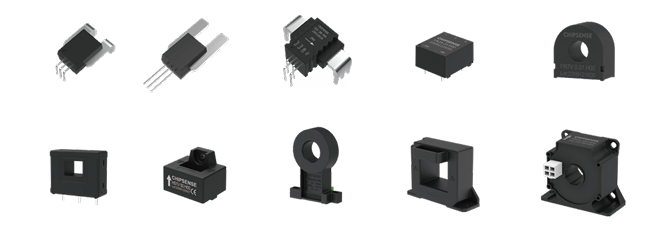
25A Low-range sensor: Rated current options include 5/6/8/12/25A, with different wiring configurations for switching ranges, suitable for precise measurement of small currents;
Wired sensor: Unlike traditional sensors with four terminals (positive, negative, measurement, ground), it has four wires: red (positive), black (negative), yellow (measurement), and green (ground). The wire to be measured must pass through the internal hole, with the hole diameter related to the range.
2. Key Considerations for Installation Wiring
Wiring Principle: Connect the secondary power supply first, then apply the primary current / voltage to avoid damaging the sensor due to incorrect power-up sequence;
Power Supply Selection: AC measurements must use bipolar power supply (positive connected to + VA, negative connected to – VA, measurement terminal M grounded through a resistor); DC measurements can use unipolar power supply (either positive or negative shorted to 0V );
Wire Passing: A single wire should ideally fill the sensor’s internal hole and be positioned centrally to achieve the best dynamic characteristics and sensitivity;
Environmental Requirements: Install in a location conducive to heat dissipation, away from magnetic materials and strong interference sources to avoid affecting the magnetic field distribution.
03
Core Operations: Application Calculations + Interference Resistance + Accuracy Improvement
1. Common Calculation Formulas (Directly Applicable)
In practical applications, the choice of supply voltage and measurement resistance will affect stability. The core formulas are summarized as follows:
-
Magnetic Balance Relationship:Ip×Np = Is×Ns
-
Output Voltage of Measurement Resistor:VM = Is×RM
-
Secondary Coil Voltage:Vs = Is×Rs (Rs is the resistance of the secondary coil)
-
Power Supply Voltage Requirement:VA = e + Vs + VM (e is the internal voltage drop of the device, which varies by model and should be checked in the manual)
If the sensor operates unstably, adjustments can be made in three ways: ① Replace with a higher voltage power supply; ② Reduce the measurement resistance RM; ③ Replace with a sensor with a smaller Rs value.
2. Interference Resistance Techniques (Proven Effective)
Hall sensors are sensitive to external electromagnetic fields, and these details can significantly reduce interference:
-
Avoid placing external wires close to the sensor; if proximity is necessary, arrange them as perpendicular to the sensor axis as possible;
-
Do not use magnetic materials for installation; choose non-magnetic brackets for fixing;
-
Prefer sensors with shielded enclosures; if shielding is not available, wrap a shield mesh around the sensor and ground it;
-
Route sensor wiring away from strong interference devices like inverters and contactors, using shielded twisted pairs for signal lines.
3. Accuracy Improvement Four Key Methods
In daily measurements, following these points can significantly enhance accuracy:
-
The primary wire must be centered in the internal hole; the greater the deviation, the larger the error;
-
Fill the internal hole with the wire as much as possible, avoiding gaps to ensure uniform magnetic field distribution;
-
The measured current should be as close as possible to the sensor’s rated value IN; if the current is too small (for example, using a 100A sensor to measure 10A), you can loop the primary wire through the internal hole 10 times (Np=10), making Np×Ip approach the rated value, which will significantly improve accuracy;
-
Regular calibration is essential, especially in environments with significant temperature variations, to avoid temperature drift effects.
4. Protective Testing (To Avoid Sensor Damage)
Although sensors have overload protection, performing these tests regularly can ensure safety:
-
Measurement Circuit Short Circuit Test:In a 25℃ environment, at rated current Ip=IN, with bipolar power supply, connect the output to ground switch, complete the switching within 1 minute, and observe if the sensor operates normally;
-
Measurement Circuit Open Circuit Test: Same conditions as above, switch connected between output and measurement resistor, check for abnormalities during switching;
-
Power Supply Reversal Test: The sensor is not powered, and there is no measurement resistor. Use a multimeter to measure between the “M terminal and the -+ terminal“; if the multimeter beeps, it indicates that the protection diode is damaged and needs replacement.
04
Summary of Applicable Scenarios and Advantages
-
Wide Applicability: Can measure DC, AC, and transient peak currents, with a range covering 5A~10000A and voltages from 5V~5000V;
-
Excellent Performance: Good linearity, wide bandwidth, fast response, and long mean time between failures;
-
Safe and Reliable: Can isolate the main circuit from the control circuit, avoiding high voltage hazards, and can also achieve overcurrent protection and current feedback functions.
Common application scenarios include variable frequency speed control devices, UPS power supplies, inverter welding machines, substations, electroplating, CNC machine tools, and power grid monitoring systems. Whenever large current detection with isolation is required, this sensor is a reliable choice!
In conclusion, Hall current sensors are not overly complex, but the details of installation wiring and interference handling directly affect measurement accuracy. Remember the core points: center the wire, match the range, power the secondary side first, and stay away from interference sources, which can basically solve most practical issues.