This is the last issue!!! Let’s give ourselves a round of applause!

This issue continues to discuss analog sensors, acoustic sensors, and information transmission modules. Let’s get started!!!
Analog Sensors:
23. AD/DA Conversion PCF8591 Sensor Module
As we all know, analog and digital signals are two opposing quantities and cannot be used interchangeably. The function of this module is to achieve conversion between digital and analog signals;
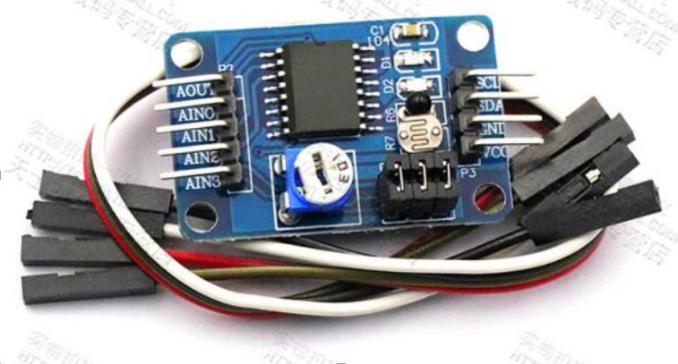 The PCF8591 chip has 4 analog inputs, 1 analog output, and 1 IIC bus (a communication protocol between different chips) interface; this means it can receive up to 4 analog signals, convert them into digital signals, and send the data through the IIC bus for external circuits to use; the 1 analog output means that the external circuit sends the digital signal to the PCF8591 chip via the IIC bus, and the chip converts the digital signal back to an analog signal, sending it to the analog output port; to use this module, the IIC bus must be utilized, which is a communication protocol between chips, and we won’t go into detailed explanations here; it also comes with selectable light-dependent resistors, potentiometers, and thermistors to collect environmental variables; this module serves as a bridge between digital circuits and analog circuits and can be used to measure voltage or current in a multimeter.
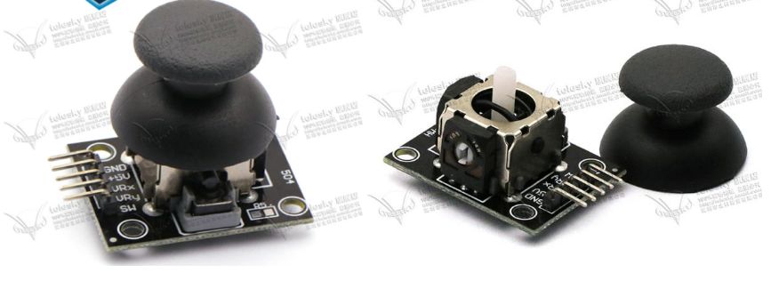
24. PS Operation Sensor Module
The PS operation sensor module has two analog output channels and one digital output interface, defined in space by the X, Y, and Z axes; the joystick’s offset in the X and Y axes will lead to a corresponding shift in the potentiometer contacts, thereby changing the resistance in the connected circuit, resulting in a voltage drop from VCC through the potentiometer, which will output at the corresponding ports of the X and Y axes, while pressing down on the Z axis will connect the microswitch beneath the joystick to GND, and this switch will output a signal at the Z axis port; since the X and Y axis outputs are analog signals, digital circuits cannot use them directly, so they generally require analog-to-digital (AD) conversion for normal use.
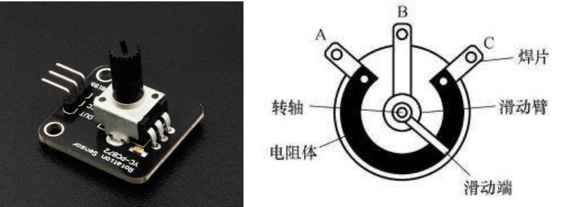
 25. Potentiometer Sensor Module
The structure diagram of the potentiometer is as follows, VCC and GND are connected to terminals A and C, and the module’s OUT pin connects to terminal B, with terminal B conducting with the sliding terminal; the resistive element has a certain resistance, and when the sliding terminal moves within its range, the voltage at terminal B has a linear relationship with the angle, allowing terminal B to obtain any voltage between VCC and GND for use in other circuits.
Acoustic Sensors:
26. Ultrasonic Sensor Module
Due to its good directionality and strong reflection capability, ultrasonic sensors are often used in military submarines’ sonar systems; the ultrasonic sensor module is a miniature version of sonar;
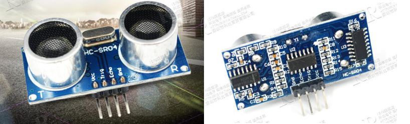
The ultrasonic sensor module is actually a highly packaged module, with the front consisting of an ultrasonic transmitter and receiver, and the back containing a complex circuit; it has 4 ports: VCC and GND provide the operating voltage, Trig is the control pin that can accept operation signals from external control circuits to start distance measurement, and Echo is the receiving end, which can respond with a certain pattern of signals based on the data measured by the module;
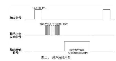
Due to its high packaging, it is actually very easy to use: the distance measurement is triggered by IO, requiring at least a 10 microsecond high-level signal to the Trig pin, as shown in the first line of the diagram (high and low voltage are evident); when the internal circuit of the module detects at least a 10 microsecond high-level signal, it starts emitting 8 pulses of 40kHz square waves from the transmitter (as shown in the second line), and automatically detects whether any signal returns; if a signal returns, meaning the receiving end receives the emitted ultrasonic waves, the ultrasonic module will keep the Echo output pin at a high level for a certain duration, and the duration is proportional to the measured distance, allowing other chips to calculate this high voltage duration to achieve accurate distance measurement; this is the complete process for distance measurement.
27. Sound Sensor Module
The sound sensor module can only detect the presence of external sounds (sensitivity adjustable) and cannot measure the loudness of sounds, while some modules have analog outputs, meaning they can recognize the loudness of incoming sounds.
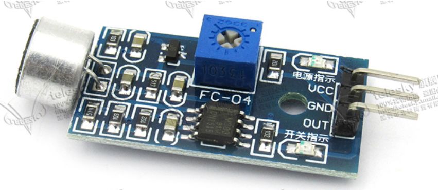
When the sound exceeds the level corresponding to the potentiometer’s position, the indicator light on the module will light up and output a low level to the OUT pin; in other cases, the OUT pin will be high; due to its response to sound, it can be used to create sound-controlled switches.
Information Transmission Modules
28. MP3 Bluetooth Decoder Board
Bluetooth is a wireless technology standard that enables short-range data exchange between fixed devices, mobile devices, and building personal area networks, operating in the 2400-2483.5MHz band, which is a globally unlicensed industrial, scientific, and medical band of 2.4GHz short-range radio frequency;
Bluetooth uses frequency hopping technology to split the transmitted data into packets, transmitting them through 79 designated Bluetooth channels. Each channel has a bandwidth of 1 MHz;
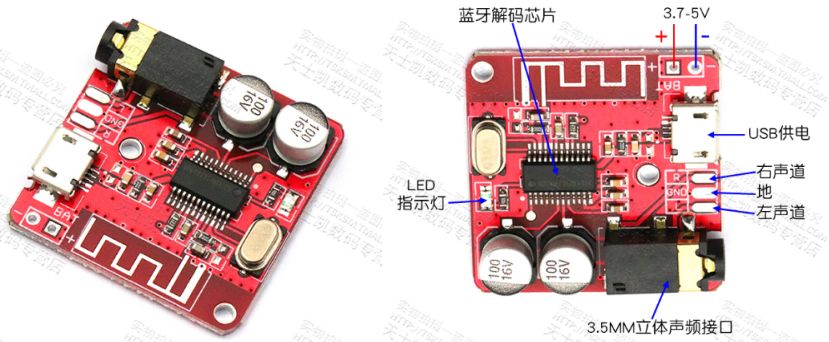
The module above is the MP3 Bluetooth decoder board, which can be used to create Bluetooth speakers and other Bluetooth audio playback devices.
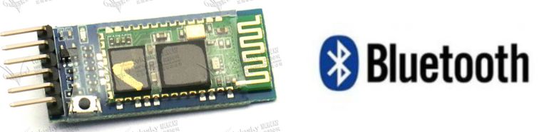
29. Bluetooth Data Module
This Bluetooth module also uses Bluetooth technology; the MP3 Bluetooth decoder board can only receive audio information sent from devices and play it from the audio terminal, while the Bluetooth module below can receive all types of information from connected devices. After successfully pairing with other Bluetooth devices, it can be used without needing to understand any Bluetooth protocols; it supports an 8-bit data format, 1 stop bit, and no parity check; the usage methods of various models of Bluetooth modules are generally similar, so we won’t go into excessive detail here; it can be used for controlling Bluetooth devices via mobile apps.
30. WIFI Module
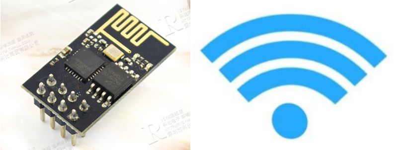
WIFI is a technology that allows electronic devices to connect to a wireless local area network (WLAN), typically using 2.4G UHF or 5G SHF ISM radio frequency bands; the WIFI module, also known as serial WIFI module, belongs to the IoT transmission layer, and its function is to convert serial or TTL levels into an embedded module that complies with WIFI wireless network communication standards; it has a built-in wireless network protocol stack of IEEE802.11b.g.n and TCP/IP protocol lines; traditional hardware devices embedded with Wi-Fi modules can directly connect to the internet via Wi-Fi, making them an important component for implementing wireless smart homes, M2M, and other IoT applications.
That’s all for the 30 sensor modules. If this has helped you, please give the article a big thumbs up, and I would be very grateful!!!

Text: Chen Feng, Li Zhengyang
Editor: Chen Feng, Li Zhengyang
Instructor: Yu Jie