Custom protocol communication is the most flexible capability of LicOS PLC/PAC in serial communication scenarios. Whether it is point-to-point communication between PLCs or interaction with third-party serial devices (such as testers, host computers, sensors, etc.), the custom protocol provides a low-threshold, customizable solution.
This tutorial is based on the attached case, guiding you through the complete process from environment preparation to data read/write in the shortest path.
Usage Scenario Description
The Free Protocol is mainly used for the following requirements:
Serial communication (RS232 / RS485) between PLCs.
Direct connection of PLC to third-party devices to implement custom protocols.
Encapsulating MODBUS RTU functionality at the user level.
The tutorial uses the MC312 controller (RS485 channel) to verify the communication environment with a serial debugging assistant.
The software used is SmartControl V5.0.
Hardware Structure (RS485)
MC312 (LicOS-PAC-MC312)
24V power supply
PC serial assistant (USB to 485)
The topology is simple: PLC ⇆ Serial Assistant
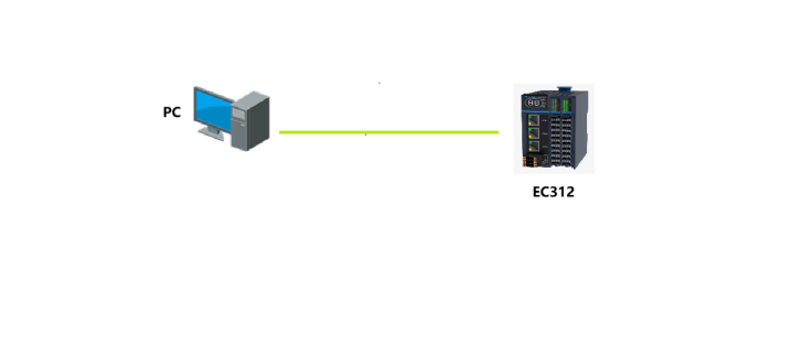
Figure 1 Network Topology
Communication Parameter Settings
After creating a new project, right-click on Device and select Add Device. The interface will appear as shown in Figure 2. Select Free Protocol COM Port, and after adding, double-click on Free Protocol COM Port to display as shown in Figure 3. Since the hardware is connected to the first port, select COM1, baud rate 9600, data bits 8, stop bits 1, no parity bit, and the send byte register is set to 0, which is address bit MW0, data starting address bit 1 which is bit MW1, and the maximum byte length can be set to the default value. The receive byte register in the figure is set to the default value MW300, data address MW301, and maximum byte length to the default value.
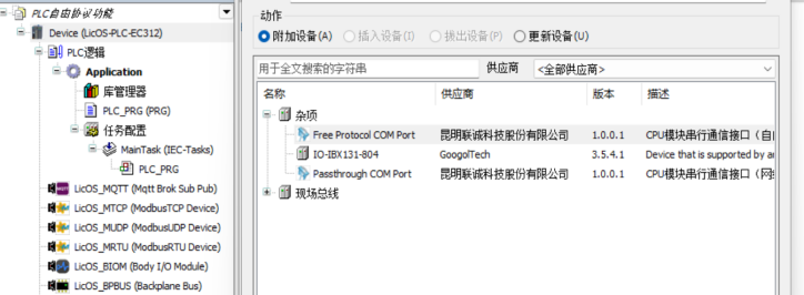
Figure 2 Configuration Application Add
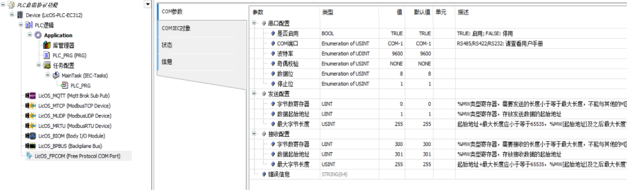
Figure 3 Communication Parameter Settings
The assistant side parameter settings are shown in Figure 4: the computer recognizes the serial port as COM6, so select COM6 as the communication port, with a baud rate of 9600, data bits of 8, stop bits of 1, and no parity bit.
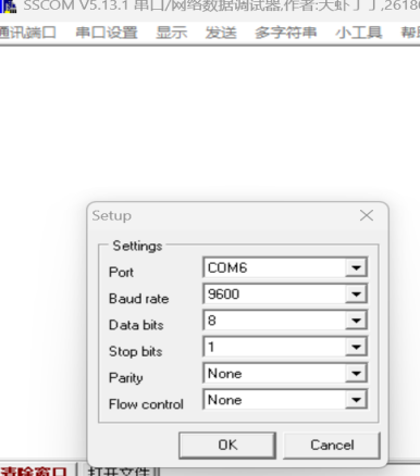
Figure 4 Serial Assistant Parameter Settings
After completing the communication parameter settings, it is necessary to map variables on the PLC side, as shown in Figure 5: it is necessary to map the send byte register address (MW0), the first address of the send content (MW1), and the receive content address (MW301). After mapping is complete, the sending mechanism needs to be set. After writing the content, writing the number of bytes to be sent will complete the sending. After sending is complete, the number of bytes sent will automatically reset to zero. The sending program is shown in Figure 6: it is set to send 10 bytes.
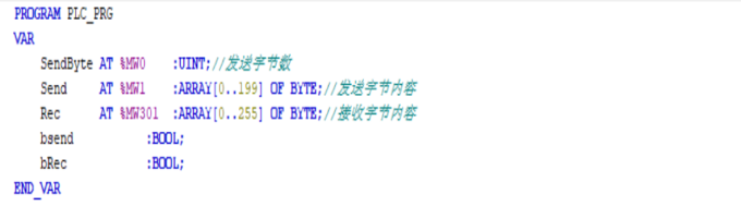
Figure 5 Variable Mapping
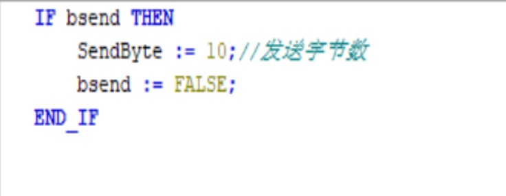
Figure 6 Sending Program Settings
Effect Demonstration
As shown in Figure 7: write the content below in the sending address, and then write the number of bytes to be sent in the sending byte address to trigger bsend. After successful sending, the byte register address value will be automatically cleared. The sending is for 10 bytes of content, and it can be seen that the assistant also receives 10 bytes of content. The content sent by the PLC and the assistant is consistent. It should be noted that each time the number of bytes is written, the content will be sent once.
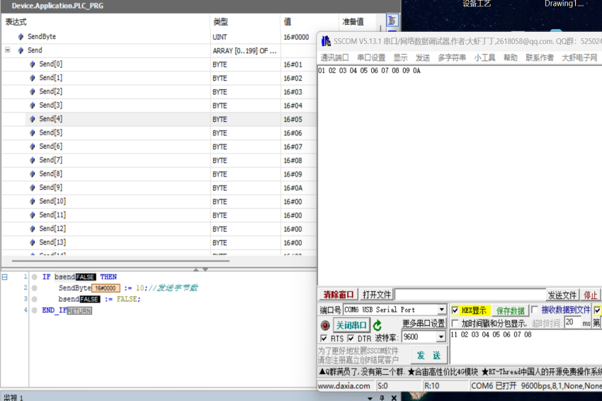
Figure 7 PLC Sending Data
The assistant sends the content shown in Figure 8. Under the premise that the PLC receives address is all 0, it will start receiving content from the first address; otherwise, it will offset and write content as shown in Figure 9, where the PLC receives the content sent by the assistant, and the data received by the PLC is consistent with what the assistant sent. Since the receive byte register has not been filled with values, it defaults to the maximum value.
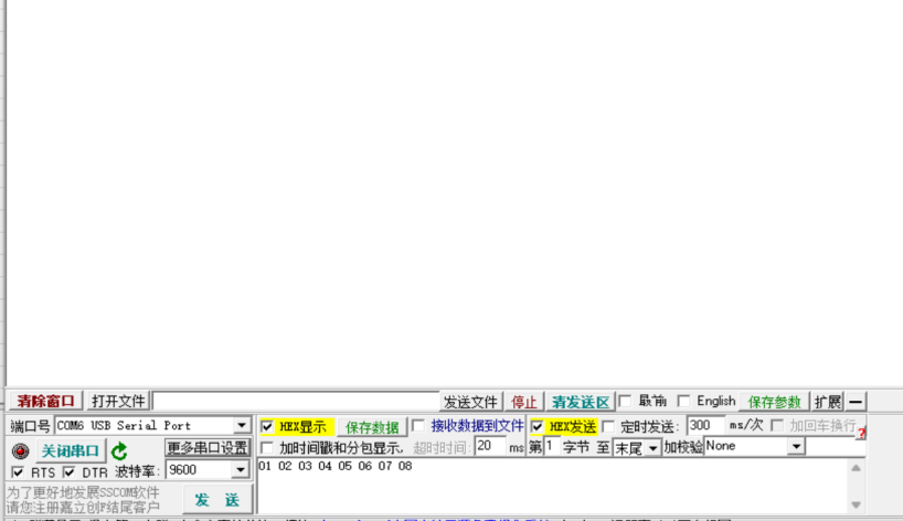
Figure 8 Assistant Sending Data
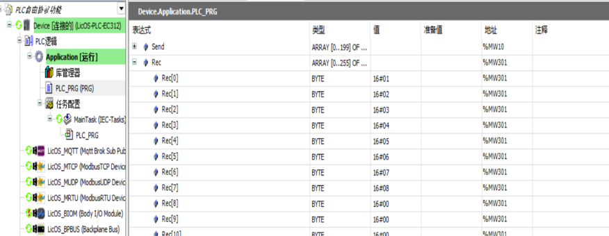
Figure 9 PLC Receiving Data
In actual projects, custom protocol communication is often used to interface with third-party devices where the protocol is not publicly available, the format is not standardized, or only example frames are provided. Using the above methods, you can quickly build a stable serial interaction link and freely encapsulate sending frames and parse receiving frames according to the actual message format, allowing the PLC to seamlessly adapt to instruments, controllers, or host computers from different manufacturers.
By mastering the core steps of this tutorial, you can “debug the free protocol and automate the protocol logic” in various serial communication scenarios, making LicOS PLC/PAC the most flexible and practical communication bridge between field devices.
If you have further technical questions, you can visit the official website of Liancheng Technology (https://www.licos.com.cn/) or consult through official technical support channels.