 Search on WeChat
 Technical Training
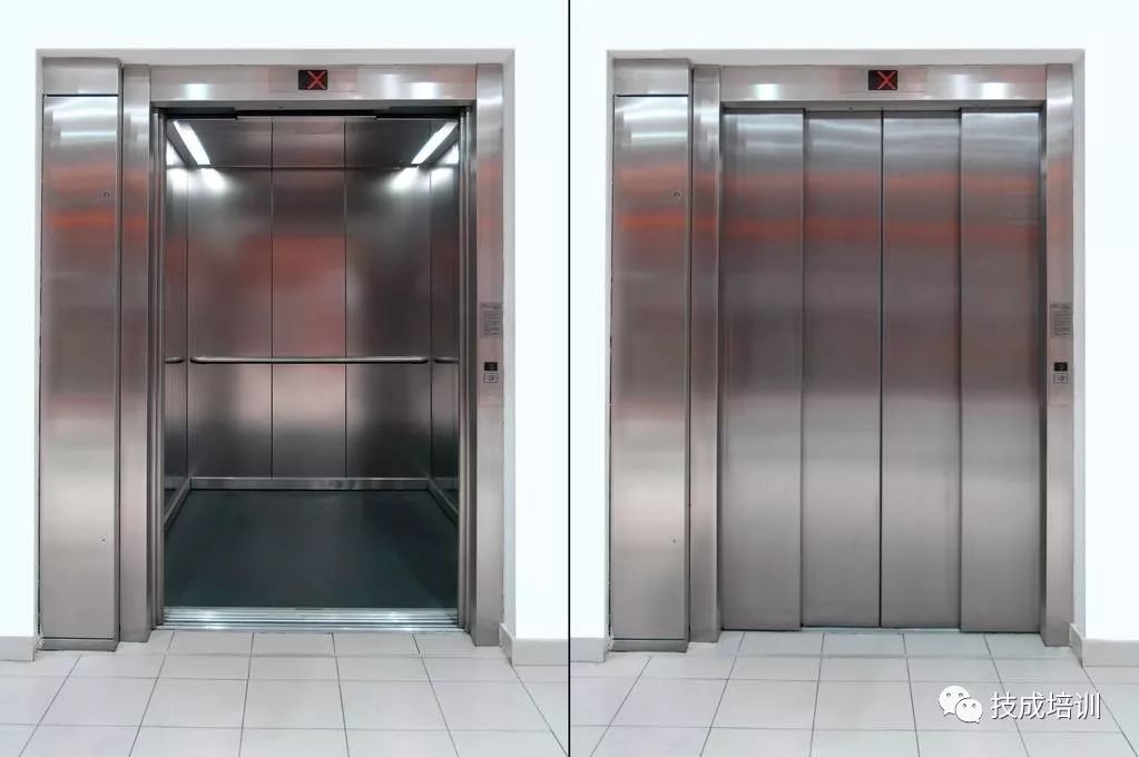
1. Basic Principles of Elevators
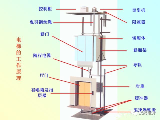
Elevators are large electromechanical products that tightly integrate machinery and electricity. They mainly consist of a machine room, shaft, cabin, door system, and electrical control system.
Rails are installed in the shaft, connecting the cabin and counterweight with traction steel ropes, which are hung on the traction wheel driven by the traction motor. The cabin and counterweight are each equipped with their own guide shoes, which fit into the rails. The operation of the traction wheel drives the cabin and counterweight to move up and down relative to each other, with the cabin rising and the counterweight descending. This allows control of the elevator’s operation—starting, accelerating, running, decelerating, and leveling—by controlling the traction motor.
2. Control Requirements
The control methods for elevators include: cabin handle switch control, cabin button switch control, external button switch control, signal control, collective control, and group control.
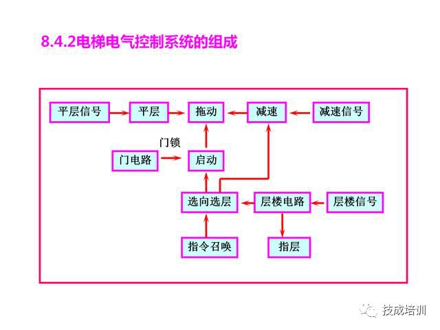
The collective control method memorizes the external call signals from the hall call box and the internal command signals from the cabin control box, and analyzes them in conjunction with other specialized signals (such as floor, deceleration, leveling, safety signals) for the elevator operator or passengers to control the elevator’s operation.
The main control requirements are as follows:
(1) Controlled by an operator or automatically;
(2) Automatic door opening and closing;
(3) When arriving at the designated stop floor, decelerate in advance and automatically open the doors at the level;
(4) When arriving at the upper and lower terminal stations, decelerate forcibly in advance;
(5) There are calling devices outside the hall, and command devices inside the cabin, which can automatically memorize calls and commands and eliminate them after responding;
(6) Can automatically select the direction of operation, and under operator control, can forcibly determine the direction;
(7) Can automatically select the stop floor based on the position of commands and calls, and automatically level the stop;
(8) There are indication signals outside the hall and inside the cabin showing the elevator’s operating direction and current position (floor detection and direction indication).
3. The Role and Implementation of Each Link in the Control System
1. Implementation of Floor Relay Circuit
To control the elevator, the primary issue is to reflect the actual position (floor) of the elevator.
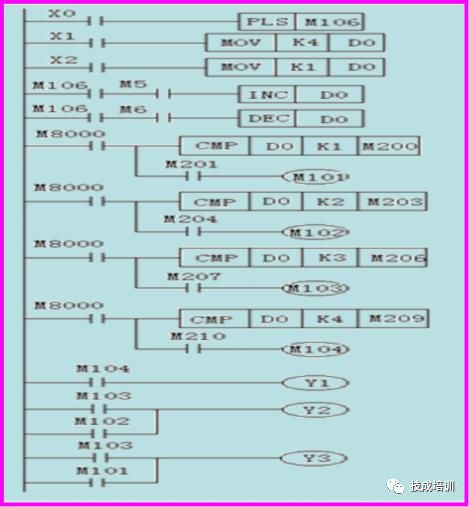
The floor relay circuit accomplishes this function. Each floor corresponds to a floor relay; when the elevator is on a certain floor, the corresponding floor relay will be activated.
PLC has functions such as data transmission, arithmetic calculation, and data comparison processing, making it easy to implement the floor circuit:
Activate a data register D0; when the elevator is at the lowest terminal station, send 1 to D0; at the highest terminal station, send the highest floor number to D0; each time the elevator ascends a floor, D0 automatically increments by 1;
each time the elevator descends a floor, D0 automatically decrements by 1, keeping the current floor number in D0;
Then, compare D0 with 1, 2, 3, …; when equal to a number, it indicates the elevator is on that floor, activating the corresponding floor relay to realize the floor circuit.
The ladder diagram for a four-floor, four-station floor relay circuit is shown below:
2. Command and Call Circuit
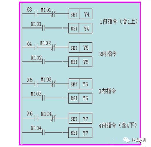
The function of the command and call circuit is to memorize and indicate the commands from the cabin and the call signals from outside the hall, and automatically eliminate them after the elevator responds; memorization and elimination can be realized using the PLC’s SET and RST instructions.
(1) Command Circuit
The ladder diagram for the command circuit is shown below:
(2) Call Circuit
Except for the two terminal stations, each other floor has two calls (up call, down call), and the call responses are sequential.
Additionally, if the elevator does not respond to a call while operating directly, the call should be retained. Therefore, the call circuit is closely related to the elevator’s operating direction and whether it is operating directly. For this reason, relays M1 and M2 that reflect direct operation and direction monitoring are added to the call circuit.
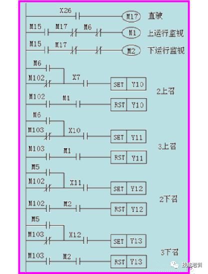
(3) Direction Selection Circuit
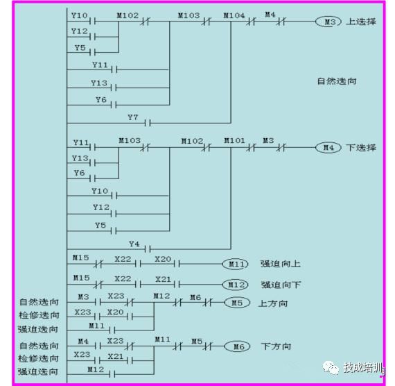
The function of the direction selection circuit is to determine the elevator’s operating direction based on its current position and the status of commands and calls, whether it is up or down.
The direction selection of the elevator is essentially comparing the positions of commands and calls with the elevator’s actual position; if the former is above (in terms of position), the elevator selects up; otherwise, it selects down.
Direction implementation: First, form a selection chain using floor relays, then connect the commands and calls for each floor accordingly.
There are three main situations that determine the elevator’s operating direction:
a. Natural Selection
As analyzed above, the elevator determines the direction itself.
b. Forced Selection
If the elevator operates in operator mode, the upward or downward button on the control panel can be used to intervene in the elevator’s operating direction, forcibly making it go up or down.
c. Maintenance Selection
If the elevator operates in maintenance mode, the upward or downward button can also be used to make the elevator operate at maintenance speed up or down. The ladder diagram for the elevator’s direction selection circuit is shown below.
3. Floor Selection Circuit
Floor selection means preparing to decelerate (change speed) for leveling. The elevator’s floor selection is divided into command floor selection and call floor selection, which determines whether the elevator stops at a certain floor based on the presence of a call or command for that floor. The command floor selection is absolute; if the elevator operates normally, the command will definitely make the elevator decelerate and stop at that floor.
The call floor selection is conditional; first, the call floor selection must meet the same direction, i.e., be consistent with the elevator’s operating direction, which is known as “forward capture”; second, during direct operation, calls can be masked, meaning that even if there are same-direction calls, they cannot make the elevator decelerate and stop.
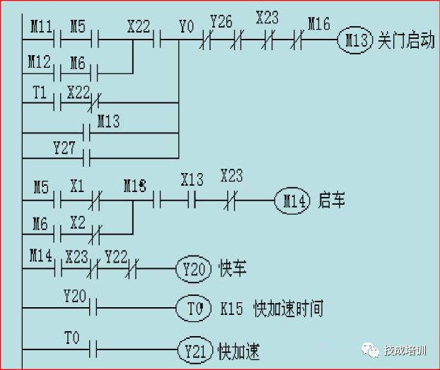
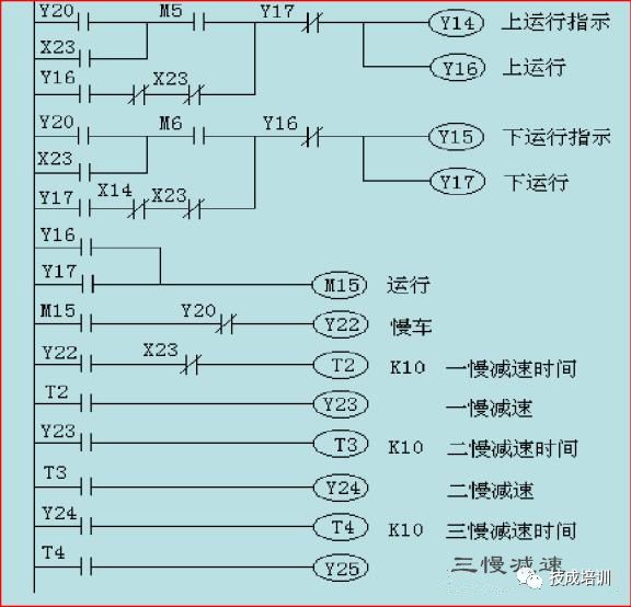
4. Elevator Operation Circuit
The operation circuit is the core of the elevator control system. The elevator is driven by a traction motor (main circuit), and the operation circuit controls the work of the main circuit to form a speed curve as shown in the figure, determining when the elevator starts to accelerate, when it runs, when it decelerates, and when it levels to stop. Therefore, the elevator’s main performance indicators (rated speed, comfort, leveling accuracy, etc.) are determined by the operation circuit.
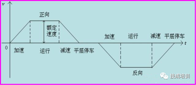
(1) Starting the Elevator: The direction is the primary condition, and safety factors such as door locks (whether the hall and cabin doors are properly closed) are also necessary.
(2) Deceleration: When the elevator selects a certain floor, it means it will stop at that floor, and it should decelerate when it reaches the speed change point in preparation for leveling.
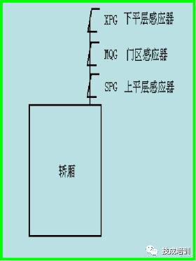
(3) Leveling Stop: When the elevator decelerates to the leveling point, it indicates that the cabin door sill and the hall door sill are basically level, and it can stop. This means disconnecting the power supply to the traction motor in the main circuit and implementing the electromagnetic brake. Generally, the leveling sensor is placed on top of the cabin, as shown in the figure. Note: When both the upper and lower leveling sensors are activated, it indicates reaching the leveling point.
5. Control of Elevator Doors
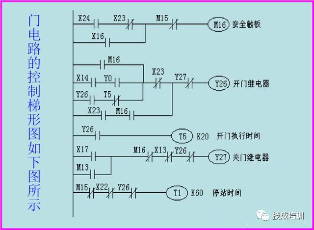
The door circuit is a relatively independent unit in the elevator control system. Its function is to control the opening and closing of the elevator doors.
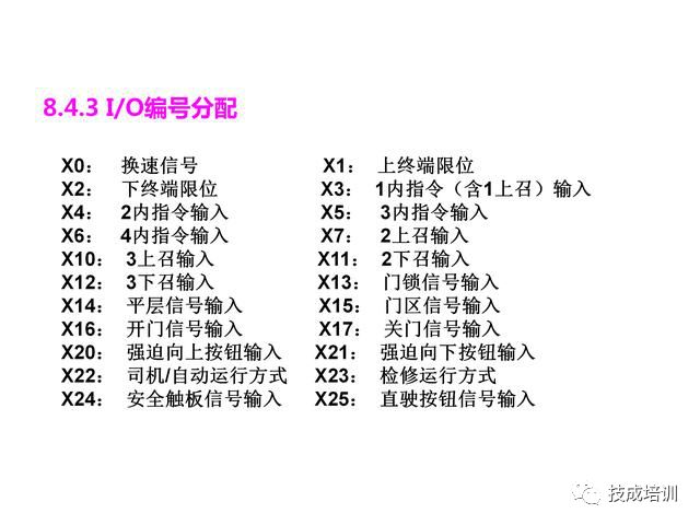
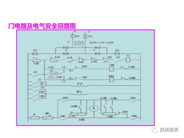
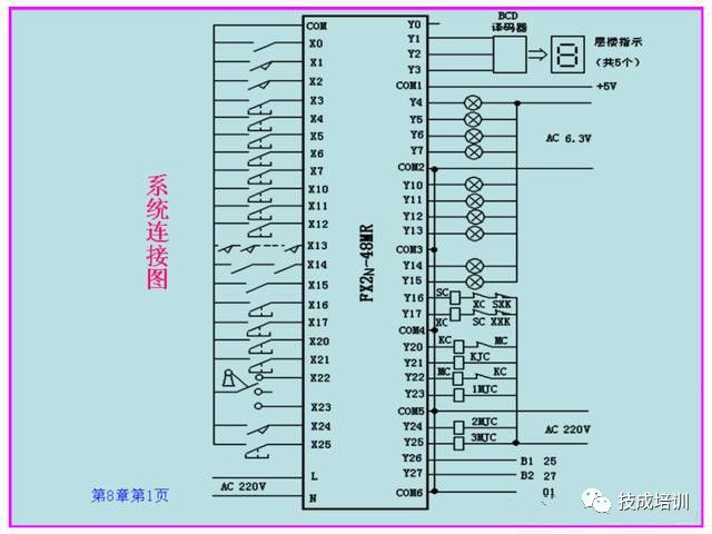
The connection between the door circuit and the control system lies in this point, where the electrical limit switches of the door locks for each hall door and cabin door are connected in series as a door lock signal (X13). When X13 is ON, it indicates that all doors are safely closed and can operate normally; otherwise, they cannot operate. The opening and closing of the doors are driven by the door motor, and the opening and closing are controlled by the door relay KMJ and GMJ to achieve forward and reverse rotation. Therefore, when designing the door control, only the opening and closing situations need to be considered, corresponding to driving KMJ or GMJ.
(1) Opening Situation
Open doors at the start of work, button to open doors, touch panel to open doors, and advance opening in the door area.
(2) Closing Situation
Close doors at the end of work, button to open doors, automatic delay closing at stops, and forced upward (downward) start to close doors.
HISTORY/Recommended Past Articles
Complete question bank for the 2021 electrical engineering junior exam (includes answers)
Having trouble diagnosing and repairing inverter faults? Just one click!
Can you brush through all electrical exam questions with one click? Don’t you have this tool yet?
Which of the five major electrical drafting software (CAD, Eplan, CADe_simu…) do you pick?
Latest electrical version CAD drawing software, with super detailed installation tutorial!
Latest electrical drawing software EPLAN, with super detailed installation tutorial!
Common issues for beginners using S7-200 SMART programming software (includes download link)
Super comprehensive electrical calculation EXCEL table, automatically generated! No need to ask for electrical calculations!
Bluetooth headsets, electrical/PLC introductory books are freely given away? Come and claim your electrical gift!
Basic skills of PLC programming: ladder diagrams and control circuits (includes 1164 practical cases of Mitsubishi PLC)
Still can’t understand electrical diagrams? Basic electrical diagram reading, simulation software available, quickly get started with theory and practice!
12 free electrical video courses, 10GB software/e-book materials, and 30 days of free electrical live classes are being given away!

Don’t forget to like + follow! 
 Click “Read Original” to learn PLC/electrical courses for free.