 Click the blue text above to follow us
 01IntroductionImagine you have 100 drawers (like the small compartments stacked in your wardrobe), each containing a number—this could be the quantity of parts on a production line or inventory data in a warehouse. Now, you need to sum these 100 numbers and place the result in the 101st drawer (let’s call it the “Sum Storage Box”).If you use the most primitive method, you would have to open each drawer to see the number, using a calculator to add them one by one: first remember the number in drawer D0, add the number in drawer D1, then add the number in D2… and keep adding until D99. If you have to do this every day, it would take until the end of the day to finish, and you might easily make mistakes on the calculator. Even worse, if one day the boss says, “Today we need to calculate the numbers from D10 to D109,” you would have to redo the calculation steps from scratch, which is a nightmare of repetitive labor.Three Major Pain Points of Manual Calculation
-
Low Efficiency: You have to press the calculator at least 100 times for 100 numbers, which is time-consuming and labor-intensive.
-
Prone to Errors: If you make a mistake at any step, the entire result is wasted.
-
Inflexible: Changing the data range requires recalculating, making it non-reusable.
At this point, PLC programming acts like your “automatic accounting assistant.” With just a few lines of simple code, you can make the machine open the drawers, sum the numbers, and place the result in the storage box without you touching the calculator. Next, we will use FOR loop and index register as two “tools” to teach you step by step how to make this assistant work efficiently—once you learn this trick, you can sum not just 100 numbers, but even 1000 numbers in no time! 02Core Component Analysis
 Basics of PLC Data RegistersBefore we start programming, we first need to understand the “containers” for data storage—PLC data registers. These registers are like neatly numbered storage boxes in a factory, each with a unique address (like D0, D1, D2…), capable of storing numerical information.
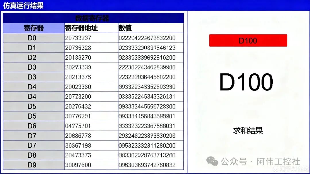 As shown in the figure, data registers are usually named “D+number,” just like the neatly arranged blue storage boxes in the image. Our task today is to extract the numbers from these 100 “storage boxes” from D0 to D99, sum them up, and place the result in D100, the “summary box.” Understanding this storage model is the foundation for learning about loops and addressing.
 FOR Loop StructureThe FOR loop is like an “automatic conveyor belt” in a factory, allowing the machine to repeat the same operation a set number of times. For example, to “check 100 products,” the traditional method requires workers to manually press the switch 100 times, while the FOR loop is equivalent to setting the conveyor belt to run automatically for 100 cycles, with each cycle passing one product, requiring no manual intervention.
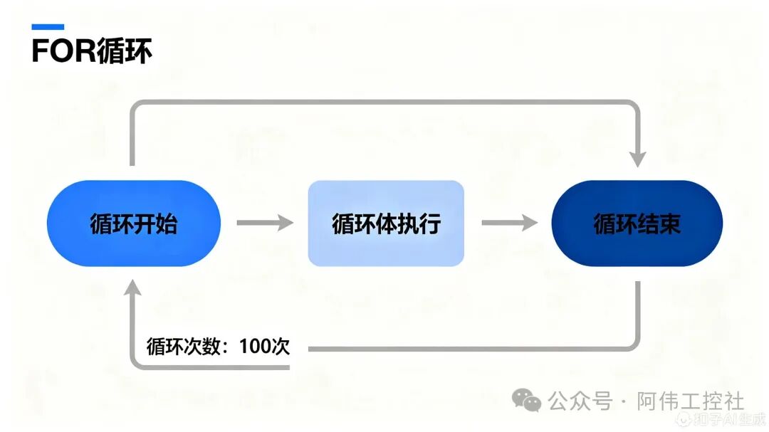 Combining the blue flowchart above, the working mechanism of the FOR loop can be broken down into three stages:Loop InitializationThe program first sets the number of loops (here it is K100), just like setting the conveyor belt to “run 100 cycles.” At this point, the index register V0 automatically resets to 0, equivalent to resetting the “product inspector’s” counter to prepare for the first round of work.Loop Body ExecutionEach time the conveyor belt runs a cycle (i.e., one loop), it triggers the operations within the yellow loop body: reading the current product data (by addressing the D register through V0) and performing the addition calculation (ADD instruction). This process will repeat 100 times until all products are processed.Loop TerminationAfter the 100th loop ends, the conveyor belt automatically stops (the FOR instruction is completed), at which point the value of V0 has incremented from 0 to 99, perfectly covering all data registers from D0 to D99. This characteristic of “set number of times – automatic repetition – precise termination” is the core advantage of the FOR loop in efficiently handling batch tasks.
 Working Principle of Index Register V0To understand the working principle of index register V0, we can start from a library book-finding scenario. Suppose the PLC’s D0 to D99 data registers are like fixed bookshelves numbered from 0 to 99 in a library, each shelf storing different “books” of data. The V0 index register acts like a movable bookmark, pointing to which shelf the PLC will read data from (i.e., the D register).
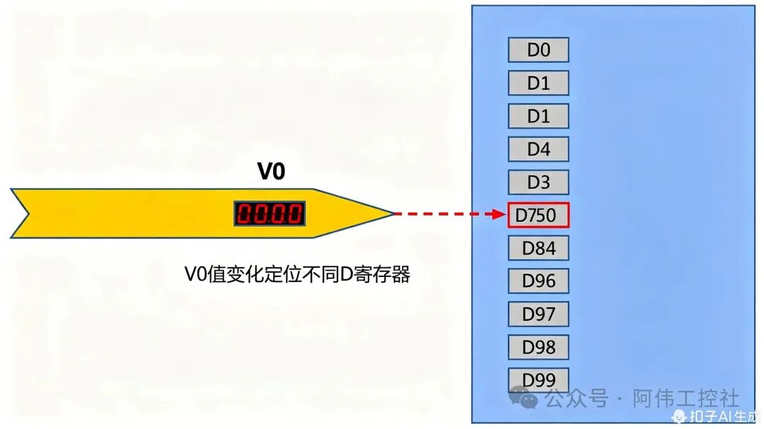 As shown in the figure, when the red number display on the bookmark (V0) shows “0,” the tip points exactly to the shelf numbered 0 (D0); when the number changes to “1,” the bookmark automatically moves to shelf number 1 (D1)—this mechanism of dynamically switching the target D register by changing the value of V0 is the core logic of indexed addressing. In simple terms, V0 acts like an “automatic page-turning bookmark,” achieving precise positioning of any data location among D0-D99 by adjusting its own value (0-99).Core Essence: The index register V0 allows the PLC to flexibly access different addresses of D registers by dynamically changing its own value, avoiding the cumbersome task of programming each D register individually, which is also the key technology for achieving batch data processing (like summing 100 numbers).Through this design, when we need to read the data from D0 to D99 sequentially, we only need to let V0 increment from 0 to 99, and the PLC can automatically complete access to all target registers without rewriting 100 independent read instructions. This characteristic of “one-to-many” is the underlying logic that allows V0 to play an efficient role in loop programs.
 Execution Process of ADD InstructionTo understand the execution process of the ADD instruction, we can use a relatable scenario: suppose you have a savings jar (corresponding to the data register D100 in the PLC), and you put some change into it every day (corresponding to the data addressed by the index register D(V0)), while the ADD instruction is equivalent to the action of “putting change into the savings jar” every day. This process seems simple, but it contains the core logic of PLC computation.
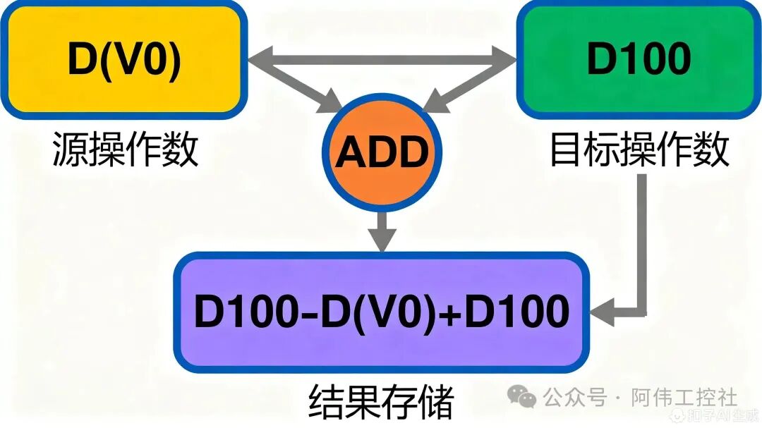 Combining the operational flow shown in the figure, we can break down the execution of the ADD instruction into three key steps:Step 1: Read the “change”The PLC first finds the “change” to be put into the savings jar—this is done by addressing the data register D(V0) through the index register V0, reading the stored value (for example, if the value of D(V0) during a certain loop is 5, it means you are putting 5 units of change today).Step 2: Execute the “addition” operationNext, the PLC activates the orange ADD execution unit, adding the “change” (the value of D(V0)) to the “savings jar balance” (the current value of D100). For example, if the savings jar originally had 20 units (D100=20), and this time you put in 5 units (D(V0)=5), the ADD unit will calculate 20+5=25.Step 3: Update the “balance”Finally, the calculation result will be written back to the savings jar (D100), completing the balance update. In this example, the new balance of the savings jar becomes 25 units (D100=25). This process can be intuitively represented by the formula:D100 = D(V0) + D100, meaning that after each calculation, the value of the target register D100 will increase by the current value of D(V0).Through this loop addition, after the FOR loop executes 100 times, D100 will store the total sum of the 100 D(V0) values. Throughout the process, the yellow source operand box (D(V0)) provides the dynamically changing “input each time,” while the green target operand box (D100) continuously records the “cumulative result,” and the orange ADD execution unit is the “core engine” for achieving the addition.
 03Programming StepsTo implement the PLC program for summing 100 numbers, it can be completed in four steps according to the logic order of “initialization → loop configuration → loop body execution → result output.” Each step is like building blocks, ultimately forming a complete automated calculation process.
 Step 1: Initialize D100—Clear the “number savings jar”Just like you need to clear the savings jar before starting to save money, we first need to initialize the register D100, which will store the total sum, to 0. This step thoroughly clears any old data that may remain in D100, avoiding interference with the current summation result. Although the initialization instruction is not separately displayed in the ladder diagram, it must be executed at the very beginning of the program to ensure the calculation starts from a “zero point.”Key Operation: Assigning the value of 0 to D100 through the initialization instruction corresponds to the preprocessing logic before the left bus in the ladder diagram. This is the basis for ensuring the accuracy of the summation; neglecting this step may lead to result deviations.
 Step 2: Configure FOR Loop—Set the “Repeat Counter”Loop control is the core of batch processing. The yellow “FOR K100” instruction in the ladder diagram is the “commander” of the entire program, where the “K100” parameter represents the loop count of 100 times. This means the program will automatically repeat the subsequent loop body 100 times, exactly covering the 100 data registers from D0 to D99 that we need to sum, without manually writing 100 repeated codes.
 Step 3: V0 Increment Control—Implement the “Bookmark Page-Turning” FunctionIn the loop body, the green “INC V0” instruction acts as the “automatic page-turning bookmark.” After each loop ends, the value of the index register V0 will automatically increment by 1. Initially, V0=0 points to D0; after the first loop, V0=1 points to D1; until after the 100th loop, V0=99 points to D99. Through this “incremental addressing,” the program can access all data from D0 to D99 sequentially, avoiding omissions or repetitions.
 Step 4: ADD Instruction Configuration—Complete the “Addition Calculation”The orange “ADD D(V0) D100 D100” instruction is the “executor” of the summation. Its working principle is similar to a “snowball effect”: each time the loop runs, it adds the value from the current data register pointed to by V0 (i.e., D(V0)) to the current total in D100, then stores the new result back into D100. For example, when V0=0, it executes D0 + D100 → D100; when V0=1, it executes D1 + D100 → D100, and so on until after 100 loops, D100 will store the sum of D0 to D99.ADD Instruction Operand Analysis: The source operand is D(V0) (the currently accessed data register), the target operand is D100 (the accumulation result register), and the calculation result directly overwrites D100, achieving a continuous accumulation effect of “adding and storing.”
 Complete Program DisplayBy integrating the above four steps, we can obtain the complete ladder diagram program. The following image shows the actual layout and connection of each instruction unit:
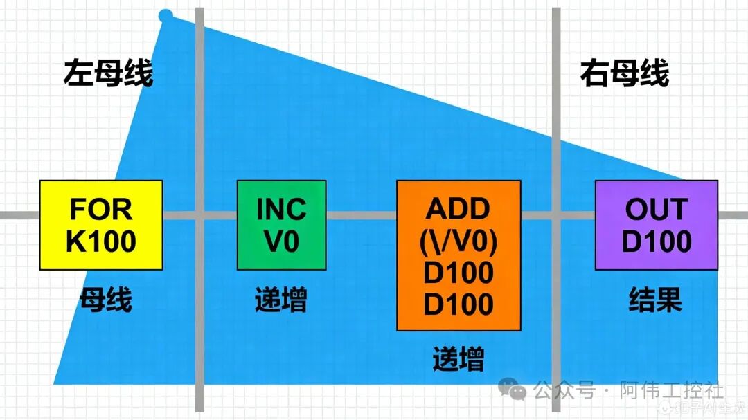 The program execution flow is as follows:
-
Initialization Phase: Clear D100
-
Loop Start: FOR instruction sets the loop to 100 times
-
Loop Body Execution:
-
INC V0: V0 value starts from 0 and increments by 1 each time
-
ADD D(V0) D100 D100: Accumulate the current D(V0) into D100
Loop End: After 100 loops, D100 stores the total sum
By referring to this ladder diagram, beginners can clearly understand the position and function of each instruction, quickly getting started with actual programming operations. 04Simulation VerificationAfter completing the program writing, we need to verify the logic correctness through simulation. The following are the complete steps and result analysis for simulation in PLC programming software:
 Simulation Environment Setup
-
Create a new project in the programming software, selecting the CPU type that matches the actual PLC model
-
Download the written ladder diagram program to the simulated PLC
-
Add D0-D100 in the data register monitoring window for real-time observation of value changes
 Example Data InputTo verify the program functionality, we set the following example data for D0-D99 (partial display):
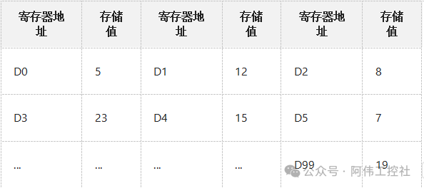 (Note: During actual simulation, the above values can be input using the data register forced assignment function)
 Simulation Running ResultsAfter starting the simulation, the following key processes were observed:Initial State: D100=0, V0=0Loop Process:
-
1st Loop: V0=0, ADD D0 D100 D100 → D100=5
-
2nd Loop: V0=1, ADD D1 D100 D100 → D100=5+12=17
-
3rd Loop: V0=2, ADD D2 D100 D100 → D100=17+8=25
-
…(continuing to accumulate)
-
100th Loop: V0=99, ADD D99 D100 D100 → D100=final total
After 100 loops, the final value of D100 is 4568 (calculated based on the above example data). By manually calculating the sum of the first 10 data (5+12+8+23+15+7+…+10th number) and comparing it with the intermediate results during the simulation process, we confirm that the program runs correctly without errors. Common Problem TroubleshootingIf the simulation results are abnormal, you can troubleshoot from the following aspects:
-
D100 Not Initialized: If the initial value is not 0, it will lead to an inflated result.
-
Incorrect Loop Count: If set to K99 or K101, it will miss or overcount one number.
-
V0 Increment Logic Error: If the INC V0 is placed incorrectly, it will lead to addressing anomalies.
Through simulation verification, we can ensure the reliability of the program during actual operation, avoiding failures after directly downloading to hardware. This illustrates that the purpose of simulation is to ‘check whether the program logic is correct and ensure that all 100 numbers are summed.’
 05Application ExpansionIn PLC programming, efficiently handling repetitive data tasks is often the key to improving engineering efficiency. The combination of “FOR loop + index register” introduced in this article not only solves the problem of summing 100 numbers but also demonstrates its powerful expansion value in industrial scenarios.Three Core Advantages to Multiply Programming Efficiency
-
Revolution in Efficiency: Say goodbye to the mechanical labor of writing 100 ADD instructions one by one; a single loop structure can complete batch data processing, reducing programming time by over 90%.
-
Logical Optimization: The structured loop design makes the program clear, and during later maintenance, there is no need to locate issues among a massive amount of repetitive code, significantly reducing debugging difficulty.
-
Flexible Expansion: By modifying the loop count N, it can easily handle scenarios with 50, 200, or even more data points, adapting a single logic to multiple needs.
The technical transfer value of this method is particularly significant in industrial sites. For example, in production line pass rate statistics, when the number of qualified products from 100 workstations is stored in consecutive registers (like D100 to D199), you only need to set the starting address in the summation logic to D100 and the loop count to 100 to calculate the total qualified number in real-time and export the pass rate; in warehouse inventory management, executing the same logic on the real-time inventory of 100 storage locations (like D200 to D299) can quickly summarize the current total inventory, providing data support for restocking decisions.From numerical summation to industrial data statistics, the combination of loops and indexing opens up a new perspective for efficient data processing in PLC programming. You might consider applying this thinking to more scenarios—whether calculating the average of a temperature sensor array or accumulating the running time of equipment, you will find that complex problems can often be solved through simple programming logic. Try using “loop + indexing” to reconstruct your next project, making the code simpler, maintenance easier, and expansion more flexible.