1. Task of PLC Technology Transformation Design for M7130 Horizontal Axis Surface Grinding Machine Electrical Control Circuit:
1. Original Circuit Analysis: First, analyze the structure, working principle, and control flow of the original electrical control circuit of the M7130 horizontal axis surface grinding machine, identifying the characteristics, limitations, and areas for improvement of the existing system.
2. PLC Transformation Scheme Design: Based on the analysis results, design a complete PLC technology transformation scheme, including:
– Selection of PLC model and I/O address allocation
– Design diagrams for the transformation of the main circuit and control circuit
– Control program flowchart and ladder diagram writing
– Design of protective measures and fault diagnosis functions after transformation
3. Evaluation of Transformation Effects: Finally, comprehensively evaluate the transformation scheme from aspects such as control accuracy, reliability, maintenance convenience, energy consumption, and cost, and provide implementation suggestions.
2. Structure Composition and Main Movements of M7130 Surface Grinding Machine
1. Structure Composition of M7130 Surface Grinding Machine
The structural composition information of the M7130 surface grinding machine (including bed 1, worktable 2, electromagnetic chuck 3, grinding wheel box (grinding head) 4, sliding seat 6, column 7, worktable reversing impact block 8, reciprocating motion reversing handle 9, vertical feed handwheel of grinding wheel box 11, piston rod 10, etc.) requires the following analysis tasks:
1. Structural Function Analysis: Detail the core functions of each main component (bed, worktable, electromagnetic chuck, grinding wheel box, etc.) and their roles in the overall operation of the machine.
2. Working Principle Clarification: Explain how these components work together to achieve surface grinding functionality, particularly the reciprocating motion mechanism of the worktable and the vertical feed principle of the grinding wheel box.
3. Key Component Relationships: Analyze the mechanical connection relationships and power transmission paths between components, such as how the piston rod drives the worktable movement and how the reversing impact block controls the direction of movement.
2. Main Movements of M7130 Surface Grinding Machine
As shown in Figure 7-16, a hydraulic drive device is installed in the box-shaped bed, and the worktable is driven by hydraulic pressure through the piston rod to perform reciprocating motion, with the bed guide rails equipped with an automatic lubrication device. The surface of the worktable has T-slots for fixing the electromagnetic chuck, which holds the workpiece being processed.
3. Technical Description of Worktable Operation and Explanation of Its Working Principle:
1. Stroke Length Adjustment Mechanism: Explain how to change the stroke length by adjusting the position of the impact block in the groove on the front of the worktable, including the adjustment process, the role of the impact block, and related mechanical principles.
2. Implementation of Reciprocating Motion: Describe how the reversing impact block changes the oil circuit through the collision of the worktable’s reciprocating motion reversing handle, thus achieving the specific workflow and hydraulic/mechanical principles of the worktable’s reciprocating motion.
3. Key Component Functions: Explain the specific roles and interrelationships of the impact block, reversing handle, and oil circuit system in the overall control of the worktable movement.
4. Adjustment Precautions: Provide safety operation points, common issues, and solutions during the adjustment process.
Regarding the description of the machine tool structure, identify its key components (bed, column, guide rails, sliding seat, grinding wheel box, grinding wheel shaft, loading electric motor, hydraulic transmission mechanism) and their connection relationships, and determine what type of machine tool this might be (e.g., grinding machine, milling machine, etc.). At the same time, explain the main functions and motion modes of each component during the machine tool’s operation.
4. Content of Mechanical Structure Operation:
1. Component Function Analysis: Detail the functions and interrelationships of the sliding seat, column guide rails, vertical feed handwheel, grinding wheel box, and transverse movement handwheel.
2. Operation Mode Comparison: Compare the two operation modes of horizontal axial movement of the grinding wheel box (transverse movement handwheel vs hydraulic drive) in terms of applicable scenarios, operational characteristics, advantages, and disadvantages.
3. Motion Adjustment Logic: Explain the specific meaning of “the former is used to adjust motion or trim the grinding wheel, while the latter is used for feeding,” and describe the typical application processes of the two motion modes in actual processing.
5. Working Diagram of Rectangular Worktable Surface Grinding Machine as shown in Figure 7-17:
The rotation of the grinding wheel is the main motion. The feeding motion includes vertical feeding, which is the up and down movement of the sliding seat on the column guide; transverse feeding, which is the horizontal movement of the grinding wheel box on the sliding seat; and longitudinal feeding, which is the reciprocating movement of the worktable along the bed. Each time the worktable completes a reciprocating motion, the grinding wheel box performs a discontinuous transverse feeding; when the entire surface is processed, the grinding wheel box performs a one-time discontinuous vertical feeding. Auxiliary movements include the rapid movement of the worktable and grinding wheel frame, etc.
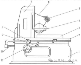
Figure 7-16 Appearance of M7130 Horizontal Axis Surface Grinding Machine
1-Bed; 2-Worktable; 3-Electromagnetic Chuck; 4-Grinding Wheel Box; 5-Transverse Movement Handwheel of Grinding Wheel Box; 6-Sliding Seat; 7-Column; 8-Worktable Reversing Impact Block; 9-Worktable Reciprocating Motion Reversing Handle; 10-Piston Rod; 11-Vertical Feed Handwheel of Grinding Wheel Box
In summary, as the main grinding tool for machine tool processing, the main motion forms can be summarized as:
1) Main Motion: The rotation of the grinding wheel.
2) Feeding Motion: Feeding motion includes: ① Vertical feeding, the up and down movement of the sliding seat on the column; ② Transverse feeding, the horizontal movement of the grinding wheel box on the sliding seat; ③ Longitudinal feeding, the reciprocating movement of the worktable along the bed.
3) Auxiliary Motion: Rapid movement of the worktable and grinding wheel frame.
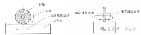
Figure 7-17 Working Diagram of Rectangular Worktable Surface Grinding Machine
The “Relay-Contactor” electrical control circuit of the M7130 surface grinding machine
The “Relay-Contactor” electrical control circuit of the M7130 surface grinding machine is shown in Figure 7-18.
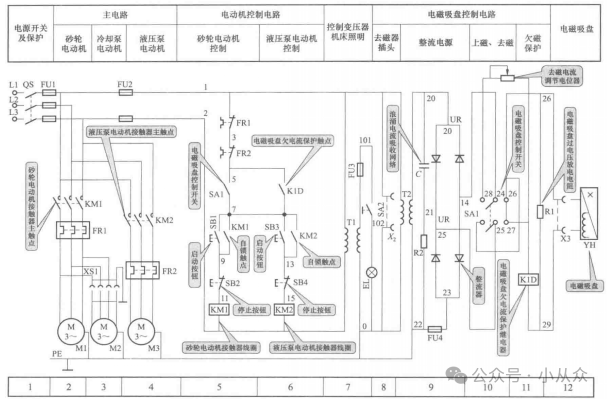
Figure 7-18 “Relay-Contactor” Electrical Control Circuit of M7130 Surface Grinding Machine
The M7130 surface grinding machine has the following control requirements for the “Relay-Contactor” motor drive:
1) Grinding Wheel Motor M1: Requires unidirectional rotation, with no speed regulation requirements.
2) Hydraulic Pump Motor M2: To ensure processing accuracy and reduce the inertial impact generated by reciprocating motion, hydraulic transmission is used.
3) Cooling Pump Motor M3: To reduce thermal deformation of the workpiece during grinding, cooling liquid must be used; the cooling pump motor has a sequential interlock relationship with the grinding wheel motor, meaning that the cooling pump motor can only be started after the grinding wheel motor is activated.
Recommended Articles
S7-200SMART PLC Analog Input Case
Servo Positioning Address Switching Position Number
Introduction and Application of FX5U PLC Bit Processing Instructions
How to Use Structured Variables to Create Panel Instances in WINCC7.5
Servo Positioning Address Switching Position Number
How S7-200SMART PLC Achieves Short and Long Button Press Control
Detailed Tutorial on Connecting PLC to WiFi Using TIA Portal Software (Windows 10)
Detailed Explanation of Using Siemens TIA Portal Library Files (Creating, Opening, Archiving, and Restoring)
It Turns Out That Communication Between S7-1200 PLC and Weintek Touch Screen DB Address Is So Simple, with Error Answers, Recommended for Collection
S7-300 Analog FC
Understanding the Momentary, Self-Locking, and Interlocking of Contactors
How to Set Programmable Buttons in ABB Robot Teach Pendant
Identifying Transformer Faults by Sound
Learning How to Apply PLC Analog Signals
Issues with TIA Portal Software Program Versions
Why Install Encoders on Motors? How Do Encoders Work?
S7-200SMART Series PLC Communication Between S7
Mitsubishi PLC Using BD Board to Control Two Inverters in Polling Case
Red and Green Traffic Light Control
Connecting Multiple Mitsubishi FX5U PLCs with Mitsubishi Touch Screen via Ethernet
Starting PLC Programming from Cylinder Control Cases
Wiring Siemens S7-1200 PLC with Servos
Connecting Omron NX with Weintek Touch Screen via Ethernet
Analysis of Mitsubishi PLC Recipe Examples
Program and Memory Structure of Siemens 200 PLC
Practical Case of Siemens S7-1200 PLC Controlling Motor Forward and Reverse Rotation
Password Protection of S7-1200 Program Blocks
How S7-200SMART PLC Achieves Short and Long Button Press Control
Siemens S7-1200 PLC Constant Pressure Water Supply Case
PLC Program Case for Motor Running for 2 Hours and Stopping for 2 Hours in Sequence