
Currently, there are numerous instruments from different brands used to measure the instantaneous flow of liquids or solids in industrial sites, which then transmit a 4-20mA signal to the PLC as a standard for control or monitoring data.The PLC calculates the accumulated flow over a certain period based on the instantaneous flow, which is significant for data analysis and yield calculation in the process control field for liquids or solids.
1. Methods for Implementing Flow Accumulation in PLC Systems
First, it must be clarified that the accuracy of flow accumulation using a PLC is far inferior to that of flow meters with built-in accumulation functions, such as electromagnetic flow meters. For flow meters with accumulation functions, the flow accumulation output is generally a pulse output, which can be counted at high speed through the high-speed pulse input of the PLC to obtain the accumulated flow.
For flow meters that only output instantaneous flow, flow accumulation addition operations should be considered within the PLC. When performing flow accumulation in the PLC, timers should not be used, as they are affected by the PLC’s scan cycle, making it impossible to achieve high precision, resulting in significant errors in the accumulated data.
Currently, most medium to large PLCs provide a “Totalizer” function block directly or indirectly, which essentially performs a simple accumulation of the instantaneous flow for each collection cycle. This article provides a specific method for introducing definite integral calculations into flow accumulation for reference.
2. Geometric Significance of Introducing Definite Integral Calculations into Flow Accumulation
Let the instantaneous flow q=q(t) be continuous over the time interval [a,b]. The flow accumulation calculation formula is:

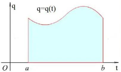
Figure 1 Instantaneous Flow
With the geometric significance of the definite integral, to find the total flow Q over the time interval from a to b, it is sufficient to calculate the area of the curvilinear trapezoid formed by the curve q=q(t), the line t=a, the line t=b, and the time axis t. By inserting several evenly spaced points within the interval [a,b]: a=t0<t1<t2<…<tn-1<tn=b, the interval [a,b] is divided into n small intervals: [ti-1, ti], and the accumulated flow over each interval length Δt can be calculated by finding the area of the i-th small curvilinear trapezoid. Each small curvilinear trapezoid can be approximated as a small trapezoid, as shown in Figure 2:
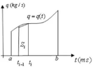
Figure 2 Instantaneous Flow Segmentation
Area Calculation:
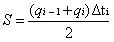
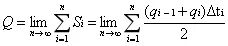
If the segmentation is infinitely fine, as the number of intervals n approaches infinity (n→∞), the total flow calculation is:
3. Specific Implementation of Integral Accumulation Flow Method in TIA Portal V15
Below, we take the Siemens PLC system’s TIA Portal V15 as an example to implement the integral accumulation flow method:
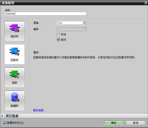
3.1 Add a new FB function block in the program directory, naming it “Totalizer”. To simplify numerical calculations, the programming language for this function block is chosen as Structured Control Language (SCL).
3.2 Open the newly created function block and establish temporary variables, as shown in the following image.
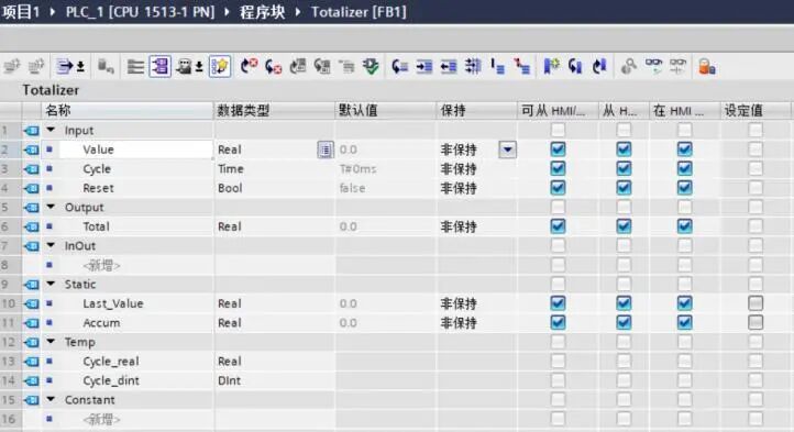
Variable Definitions:
Variable Name: Reset, Data Type: Bool, Group: Input, Purpose: FB receives external commands to reset accumulation;
Variable Name: Value, Data Type: Real, Group: Input, Purpose: FB receives external instantaneous flow data. It should be noted that the unit of instantaneous flow for general flow meters is m3/h, which needs to be converted to m3/s by dividing the instantaneous flow received by the PLC by 3600 before inputting here;
Variable Name: Cycle, Data Type: TIME, Group: Input, Purpose: FB receives the program cycle time, unit: seconds,
Here, the Cycle value is the cycle time of the interrupt block OB30.
Variable Name: Last_Value, Data Type: Real, Group: Static, Purpose: Static storage of the instantaneous flow value from the previous scan cycle;
Variable Name: Accum, Data Type: Real, Group: Static, Purpose: Static storage of the accumulated flow value;
Variable Name: Cycle_DInt, Data Type: Dint, Group: Temp, Purpose: Temporarily stores the value of Cycle converted to Dint data type within the FB;
Variable Name: Cycle_Real, Data Type: Real, Group: Temp, Purpose: Temporarily stores the value of Cycle_DInt converted to Real data type within the FB;
Variable Name: Total, Data Type: Real, Group: Output, Purpose: FB transmits the accumulated flow value to the outside.
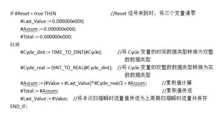
3.3 Program Writing, as shown in the following image:
After completing the program writing, compile it. If there are no errors in the compilation, it can be called.
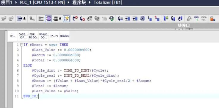
3.4 In the flow calculation function FC, call the FB block named “Totalizer” and assign values to the input and output parameters, as shown in the following image:
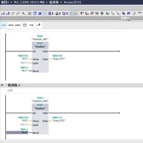
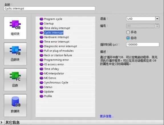
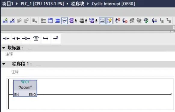
3.5 In OB30, call the flow calculation FC function block. The OB30 interrupt block is a cyclic interrupt block, with a cycle time set to 100ms, as shown in the following image:
3.6 Program Interpretation
4. Other Issues in Flow Calculation within PLC Systems
The above program is just a simple example. In practical applications, more complex issues need to be considered based on actual situations, such as:
▶ For the integral algorithm, using small rectangles to accumulate flow, the finer the rectangle divisions (i.e., the shorter the OB30 cycle time), the smaller the error. It is impossible to have no error.
▶ If the flow meter itself has an accumulation function and can output instantaneous flow in an analog manner (e.g., 4-20mA), but cannot send out the accumulated flow value, then the accumulated flow value from the flow meter may differ significantly from the accumulated flow value in the PLC. This discrepancy can be caused by various factors, excluding the system’s accumulated flow error. If the PLC system is powered off for maintenance or related modules are replaced while the flow meter continues to measure, the PLC cannot accumulate this portion of the flow.
▶ Automatic and manual resetting of accumulated values to prevent data overflow. The timing for automatic resetting should be carefully considered in conjunction with the program.
▶ When programming flow accumulation, avoid performing operations between floating-point numbers with vastly different magnitudes. If timely resetting is not done, the flow accumulation program may initially run normally, as both the initial accumulated flow value and instantaneous flow value are small floating-point numbers, resulting in a correct sum. However, after some time, as the accumulated flow value increases significantly, when it differs greatly from the instantaneous flow value, the instantaneous flow value will be ignored during addition (e.g., adding 9999990.0 and 0.2). Those familiar with computer science should be aware of this issue, which arises from the storage mechanism of floating-point numbers. This problem can be addressed by using secondary or multi-level accumulation methods, where each level of accumulator can only accumulate data within a specified range. When the accumulated data in the first-level accumulator reaches a certain threshold, it is immediately transferred to the second-level accumulator, and the first-level accumulator is reset.
Source/China Industrial Control Network, for reprints please contact
Previous Issues · Recommendations
PID Process Flow Diagram, these key points are crucial!
Disassembly and repair of electric screwdrivers (De Rui DR-D01A2) and lithium drills, solving issues of not turning on and weak rotation.
[Master Tutorial] 12000 minutes Microcontroller Implementing Modbus/MQTT/PLC Dedicated Communication Protocol to take you from novice to expert!
187 basic circuit diagrams, after reading, don’t say that electricians are hard to be!
How much do you know about terminal block knowledge points?

Share, view, and like, at least I want to have one!