Overview:The implementation method involves connecting field thermocouples to the temperature acquisition module, which connects via RS-485 to a serial server. The serial server converts the RS-485 signal to Modbus TCP protocol, allowing the DCS to collect data from the serial server.
Main Tasks: Configuration of the multi-point temperature acquisition module; configuration of the serial server; configuration of the PKS system.
1.The multi-point temperature acquisition module uses the DAM-5521, capable of collecting temperatures from 24 thermocouples on-site. The collected data is transmitted via Modbus serial communication as either engineering values or raw values, with the temperature acquisition module acting as a Modbus slave.
This module is easy to set up, with all operations performed through a graphical interface. Required tools: a Windows computer; if the computer does not have a serial port, a USB-to-serial cable is needed, along with the temperature acquisition module configuration software. The setup steps are as follows:
Install the USB-to-serial driver, open the computer’s Device Manager, right-click on the communication port under Ports, and enter properties to configure. Configuration parameters are referenced in Figure 2.
Figure (1):
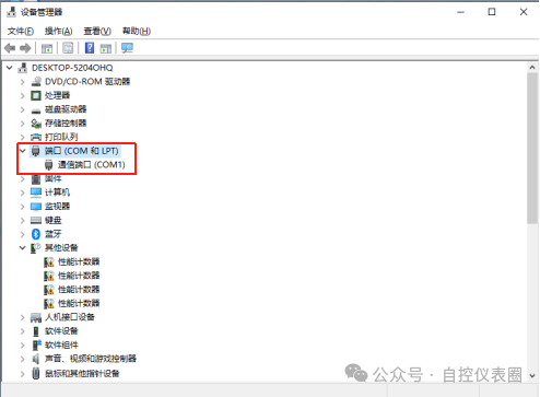
Figure (2)
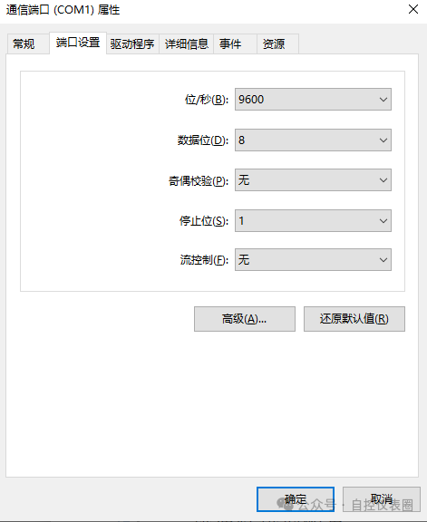
Wiring the module, enter configuration mode, and according to the manual, short the CFG+ and CFG- terminals while powering on. Then, open the dedicated configuration software, click on the first area in Figure (3) to pop up the serial communication settings, set it to match the computer parameters, and select the corresponding serial port in the red box in Figure 4. In the fifth area, select address 1 in configuration mode, and click connect:
Figure (3):
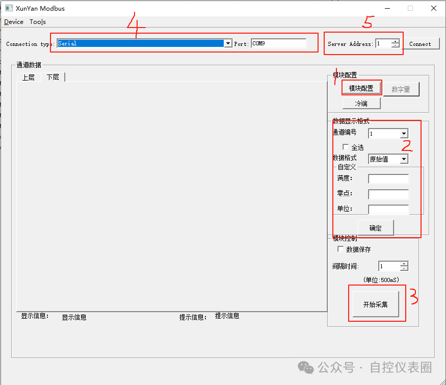
After successfully connecting the device, click on module configuration again to enter the parameter settings inside the module. Here, set the thermocouple type to K, the data format to raw value (unsigned 16-bit integer, 0x0-0xFFFF), and set the device address to 8 (required for communication with PKS). After configuration, you can select all channels to read data in the second area of the above figure, choose the data format as raw value, confirm, and then click the start acquisition in the third area of the above figure. Since no thermocouple is connected, it shows the maximum value ffff, indicating successful communication configuration.
Figure (4):
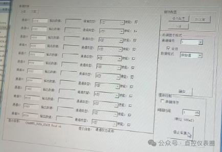
If you choose to read engineering values, it will display the actual temperature, as shown in the following figure:
Figure (5)
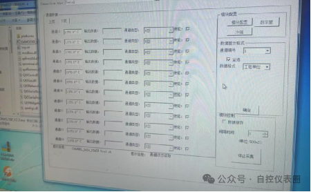
At this point, the module configuration is complete. Disconnect the power, remove the shorting wire from configuration mode, and power on again for verification. Note that the address in the fifth area of Figure (3) needs to be set to the previously configured 8. If reading is normal, it indicates that the multi-point temperature acquisition module has been successfully configured.
2.Configuration of the Serial Server
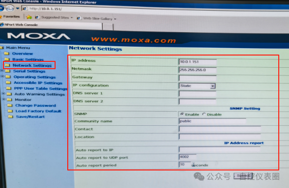
The multi-point temperature acquisition module only supports RS-485 communication, while the PVC plant PKS system only supports Modbus TCP protocol. The role of the serial server is to convert the two-wire RS-485 to Modbus TCP protocol. Required tools: serial server (NP5630, 16 ports), computer. Enter the IP of the serial server in the browser to access the serial server configuration page, select network configuration, and configure the IP and subnet mask; other settings are default as shown in the figure below:
Figure (6)
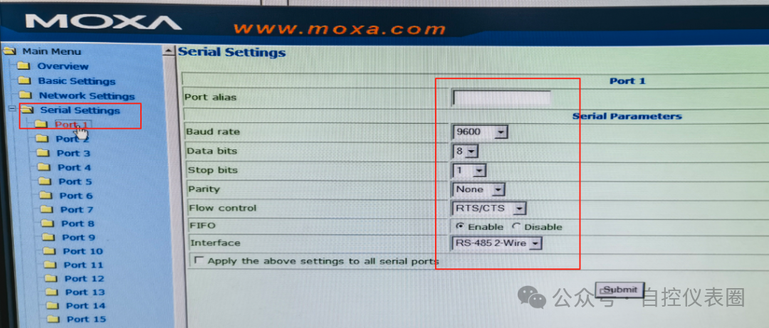
Enter the serial port configuration as shown below; parameters must match those of the temperature acquisition module.
Figure (7)
The final step is to enter the serial mode configuration. Since the temperature acquisition module is a slave, select Server mode here. If using the first port, set the local TCP port to 4001, as shown in the figure below:
Figure (8)

At this point, the serial server configuration is complete.
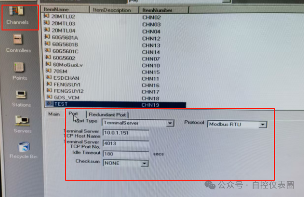
3.DCS System Configuration: Open the PKS system’s quick builder, configure the channel, set the IP, and select server mode. Using the 13th port, the TCP port number is 4013, as detailed in the figure below:
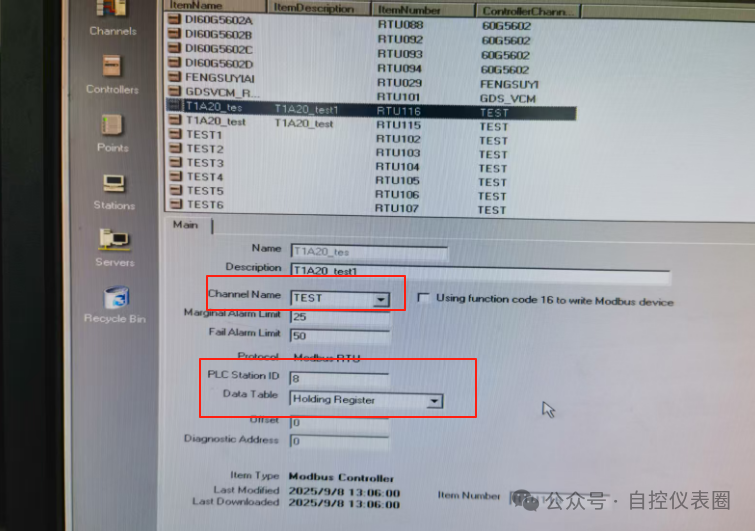
After configuring the channel, configure the controller. At this point, select the TEST channel we configured in the previous step, set the PLC station ID to the temperature acquisition module’s address 8, and select the data type as HOLDING REGISTER (according to the temperature acquisition module’s manual), as shown in the figure below.
Figure (9)
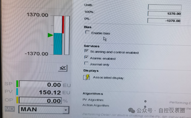
The final step is to configure the points, as shown in Figure (10). The key is the address, which consists of the controller name, address, and data format. In the PKS system, unsigned 16-bit integers are represented as U16B. The range is calculated according to the manual, as shown in Figure (11). The hexadecimal 0x8000 corresponds to 0°C, and 0xFFFF corresponds to 1370°C, resulting in a range of -1370°C to 1370°C for input.
Figure (10)
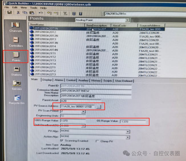
Figure (11)

After downloading, open the station and enter the configured point details to check if the data is normal. The following figure shows normal communication.