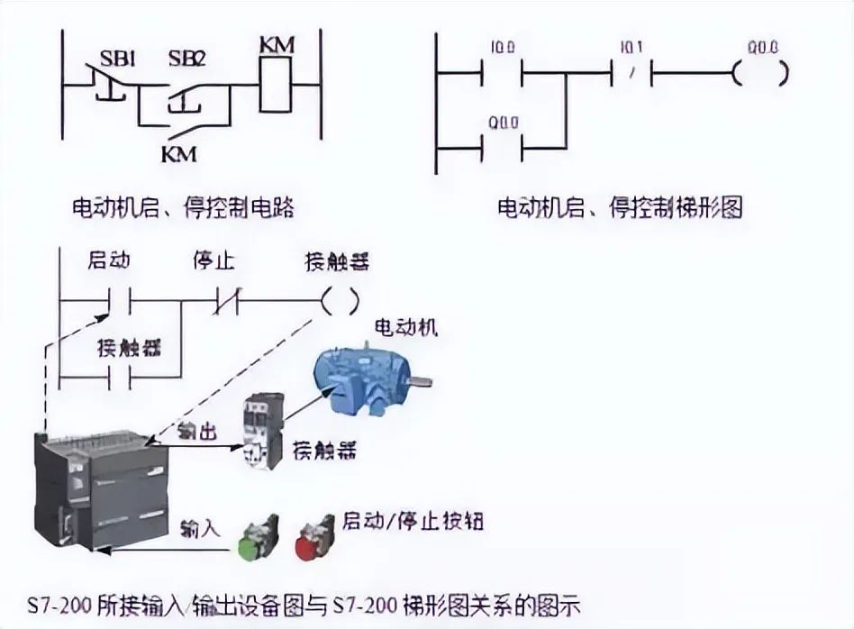
Single Output Self-Locking Control Circuit
The start signal I0.0 and the stop signal I0.1 are typically ON for a short duration. The main feature of this circuit is its “memory” function.
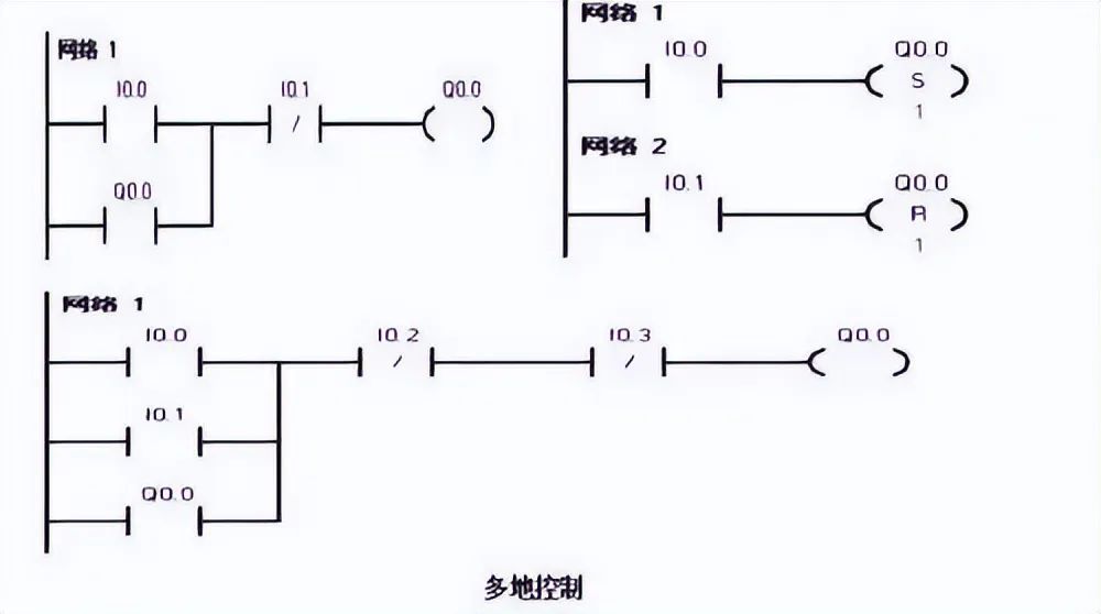
Example 2Multi-Output Self-Locking Control Circuit (Set, Reset)
The multi-output self-locking control means multiple load self-locking outputs, which can be programmed using set and reset instructions.
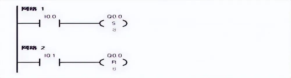
Example 3Unidirectional Sequential Start-Stop Control Circuit
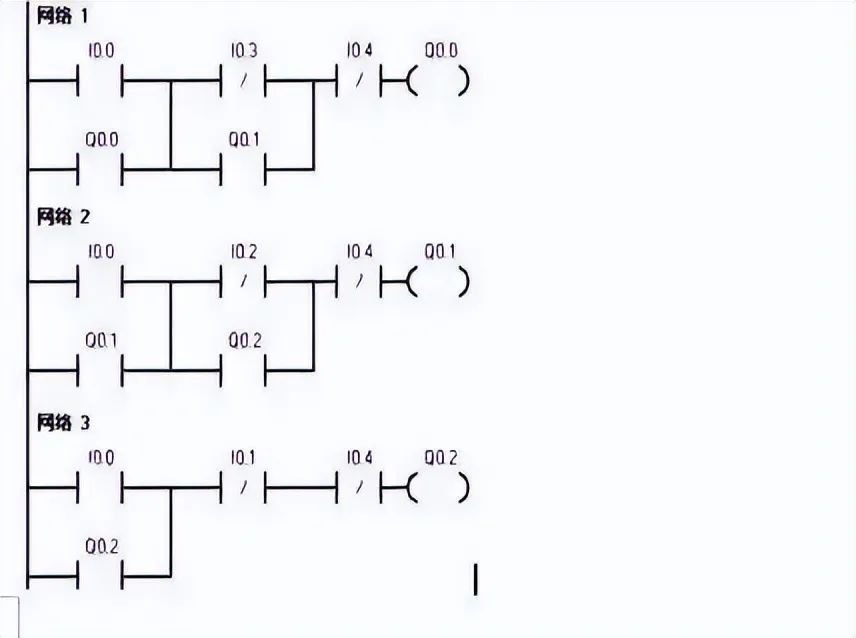
1. The unidirectional sequential start control circuit operates in a predetermined order according to the production process, with each actuator automatically operating in sequence under the influence of various input signals. Only after Q0.0 starts can Q0.1 start, and Q0.2 can only start after Q0.1 has completed.

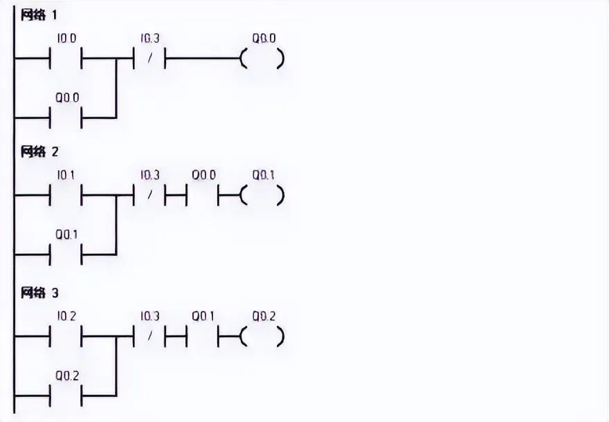
2. The unidirectional sequential stop control circuit requires that the actuators be stopped in a specific order. Q0.2 must be stopped before Q0.1 can be stopped, and to stop Q0.0, Q0.1 must be stopped first. I0.4 is the emergency stop button.
Example 4Delay Start-Stop Control Circuit
1. The delay start control designs a delay start procedure using the self-locking state of the intermediate relay (internal memory M) to allow the timer to count continuously. When the timing period is over, its normally open contact acts, causing Q0.0 to operate.
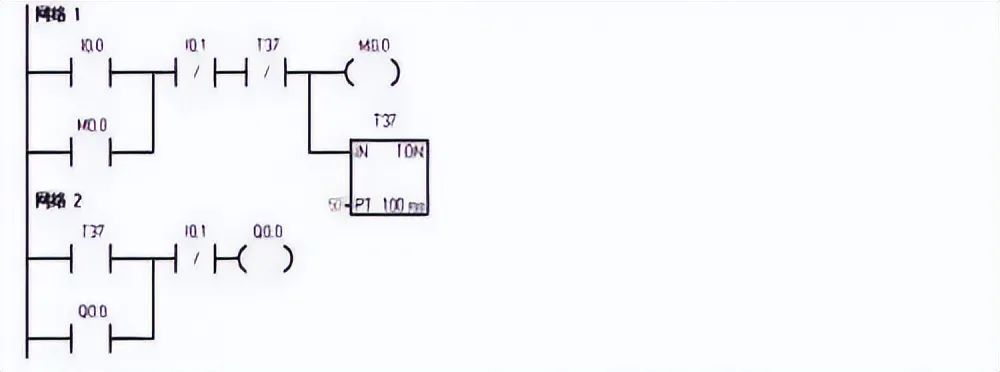
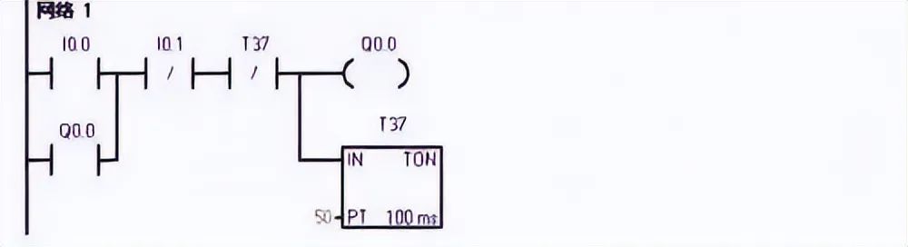
2. Delay stop control occurs after the timing period is over. I0.0 is the start button, and I0.1 is the stop button.
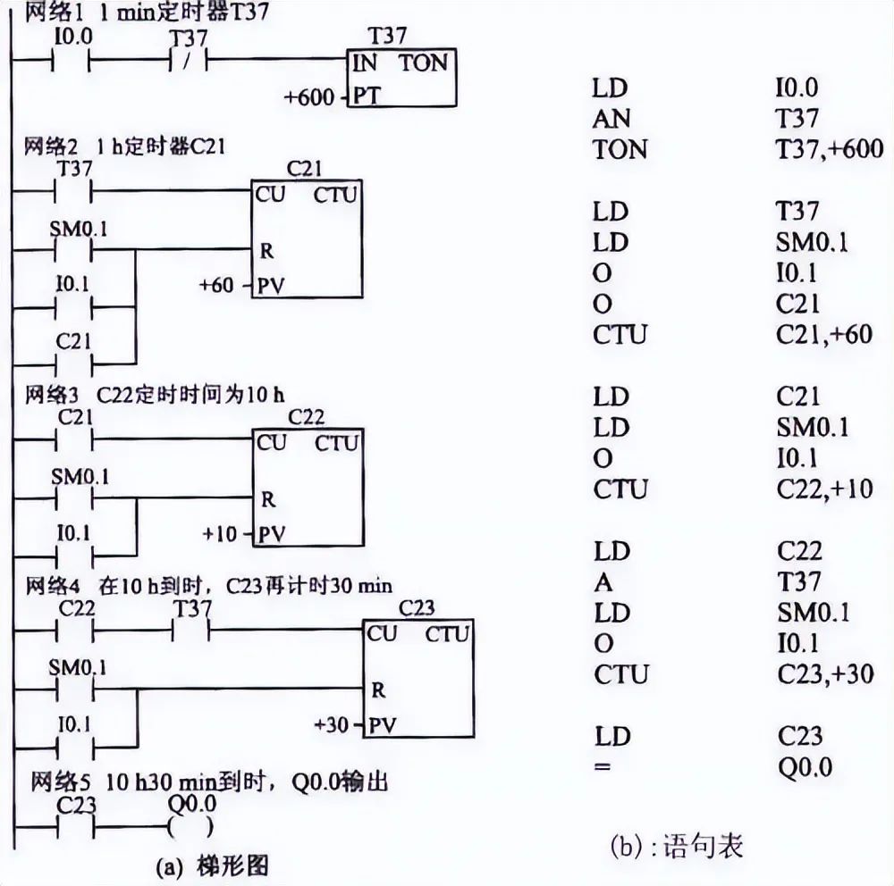
3. The delay start-stop control circuit requires that after receiving an input signal, the output signal remains OFF for a period of time before turning ON; conversely, after the input signal is OFF, the output signal remains ON for a period of time before turning OFF. T37 delays 3 seconds as the start condition for Q0.0, and T38 delays 5 seconds as the cutoff condition for Q0.0.
Experience DesignMethodsand Precautions
During the application program design process, it is essential to correctly select parameters that reflect changes in the production process as control variables; the interlocking relationships between actuators and programming components must be correctly handled. There are various design methods for application programs, commonly used methods include experience design and sequential function chart methods.
1 Experience Design Method
The experience design method requires the designer to have rich practical experience and a good grasp of the basic links of many typical application programs. Based on the requirements of the controlled object for the control system, the designer selects basic links based on experience and organically combines them. The design process is gradual and generally does not yield the optimal solution. After the initial design of the program, it needs to be repeatedly debugged, modified, and improved until it meets the control requirements of the controlled object.
The experience design method is not standardized and lacks a universal rule, possessing a degree of trial and randomness.
Rules to Follow When Writing Ladder Diagram Programs:
(1) The state of the “input relay” is driven by the switch signal of external input devices, and the program cannot arbitrarily change it.
(2) In the ladder diagram, the same numbered “relay coil” can only appear once; it typically cannot appear again, but its contacts can be reused infinitely.
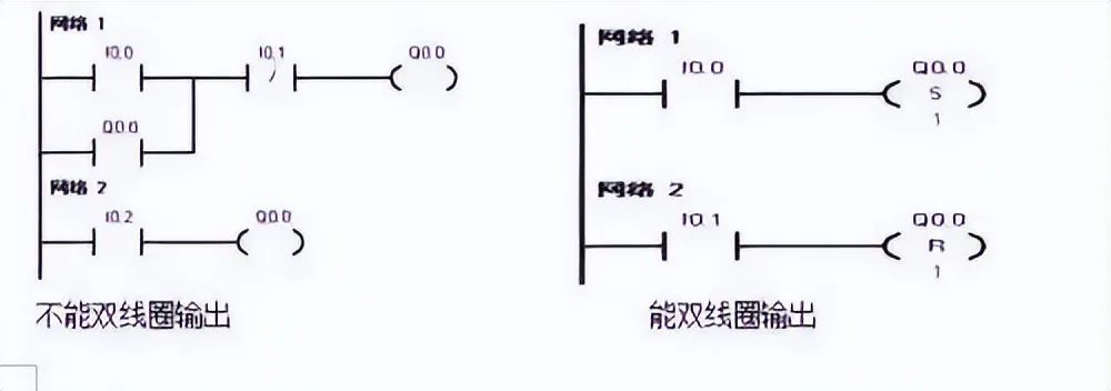
Rules to Follow When Writing Ladder Diagram Programs:
(3) When several series branches are in parallel, the branch with more contacts should be arranged on top; when several parallel circuits are in series, the branch with more parallel branches should be arranged on the left. Ladder diagrams created following this rule can reduce the number of user program steps and shorten the program scanning time.
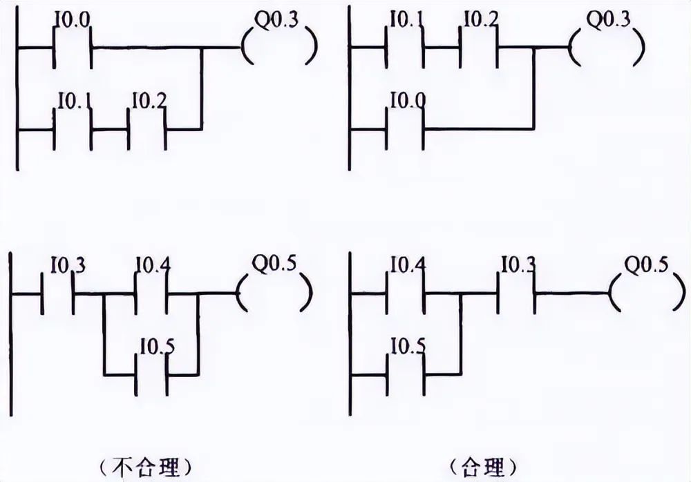
(4) The program should be arranged from left to right and from top to bottom. A ladder rung begins at the left bus and terminates at the right bus, with the coil directly connected to the right bus.
① Bridge circuits must be modified before a ladder diagram can be drawn.
② Non-bridge complex circuits must be modified before a ladder diagram can be drawn.
2 Precautions
(1) First compile the I/O allocation table, then design the ladder diagram. First, number and allocate the input, output signals, and internal coils, then determine the actual wiring diagram for each PLC input/output terminal.
(2) Reasonably arrange the ladder diagram to prevent input/output response lag from affecting actual response speed. Typically, output coils are arranged in the order of actions according to the process flow diagram, while also considering the arrangement of internal coils, time relays, and so on, so that the delayed response of input/output does not affect the actual output’s response speed requirements.
(3) High-speed counting instructions and high-speed pulse output instructions should be placed at the beginning of the user program as much as possible. Since the information exchange between the high-speed counter and the high-speed pulse generator and the CPU occurs during I/O scanning, executing other commands may affect this information exchange, potentially causing pulse loss.
(4) In the PLC input terminal wiring diagram, for the same signaling element, typically only one contact (e.g., normally open or normally closed) needs to be connected to the input terminal, meaning that one signaling element can only occupy one input address number.
(5) Reasonably connect the input signal contacts (normally open or normally closed) to improve the reliability and safety of the equipment. In the actual PLC I/O wiring diagram, whether a certain input signal (e.g., button) is connected to the normally open contact or normally closed contact should be considered from the perspective of equipment reliability and safety. When a wiring fault occurs at the input terminal, the equipment state should shift towards a safe state. Therefore, the stop button should be connected to the PLC input terminal using a normally closed contact, while the start button should be connected using a normally open contact (for ease of understanding, all diagrams in previous chapters of this book have been treated as normally open contacts).
(6) For safety reasons, major safety components should not be connected to the PLC’s input end but should be handled with hardware. For example, emergency stop buttons, interlock contacts, emergency limit switches, thermal relay control contacts, etc., should be connected to the PLC’s output terminals to directly control the output load (KM1, KM2), ensuring that PLC failures do not damage equipment or cause serious safety incidents.
(7) Ensure that the effective input signal’s level holding time is maintained. To ensure the input signal is valid, the level holding time must be greater than one PLC scanning cycle. Unless the switch input signal has the pulse capture function enabled, which allows the PLC to capture very short-duration pulses.
(8) The execution conditions of PLC instructions differ between valid signal levels and edge triggering, which should be noted during programming.
(9) When converting from electrical control diagrams to ladder diagrams, it should be noted that for retrofitting old equipment, the original relay control circuit diagrams can be referenced for conversion to ladder diagrams. The electrical contacts in relay control circuit diagrams are mostly of the break-then-make type, while the normally open and normally closed contacts of “soft relays” in PLC ladder diagrams change states simultaneously. When designing ladder diagrams, delay circuits (e.g., using internal time relays for delays or utilizing the PLC’s cyclic scanning working mode to produce input/output delayed responses) can simulate the functionality of break-then-make electrical components.
Sequential Function Chart and Design MethodFunction Chart and Its Components
The Function Chart Diagram is a universal language that combines graphical symbols and textual descriptions to comprehensively describe control systems, including electrical, hydraulic, pneumatic, and mechanical control systems or control processes, functions, and characteristics of certain parts of the system. In a function chart, a process loop is broken down into several clear sequential stages, called “steps”. Steps are separated by “transitions”. When the transition conditions between two steps are met and the transition is achieved, the previous step’s activity ends, and the next step’s activity begins. The more steps a process loop has, the more precise the description of the process.
1. Step
In a working cycle of the control system, sequentially connected working phases are called steps or work steps, represented by rectangular boxes with text (or numbers). Steps have two states: “active step” and “inactive step”. A series of active steps determines the state of the control process. Each function chart must have at least one initial step, which is represented by a double-lined rectangular box.
2. Action
In the function chart, commands (Actions) are represented by rectangular boxes with text and letter symbols, connected to the corresponding step symbols. An activated step can lead to one or several actions or commands, meaning that the actions corresponding to the active step are executed. If a step is inactive, the corresponding actions revert to the state prior to the activation of that step. All actions corresponding to the active step are executed, and the actions of the active step can be the start, continuation, or end of actions. If several actions are connected to the same step, these action symbols can be arranged horizontally or vertically.
3. Directed Connections
Directed connections link steps in the order of progress, connecting steps to transitions and transitions to steps. Directed connections specify the direction and route of progress from the initial step to the active step. Directed connections can be arranged vertically or horizontally. To make the diagram clearer, they can occasionally be represented with slanted lines. In function charts, the direction of progress is always from top to bottom, left to right, so directed connection arrows can be omitted. If these progress rules are not followed, arrows must be indicated. Directed connections can cross if there is no intrinsic relationship between vertical and horizontal directed connections, but crossing is not allowed when directed connections are related to the same progress. When drawing function charts, if the diagram is complex or if several diagrams are needed to represent directed connections that must be interrupted, the next step number and its page number must be indicated.
4. Transition
In the function chart, the generation of active steps progresses along the route specified by directed connections, and this progress is completed by the realization of one or several transitions. The transition symbol is a short line intersecting with directed connections, separating adjacent steps. If all preceding steps connected by directed connections to the transition symbol are active steps, the transition is an “enabling transition”; otherwise, it is a “non-enabling transition”. Only when a transition is an enabling transition and its conditions are met can it be realized. When a transition is realized, all subsequent steps connected to the directed connections and corresponding transition symbols are activated, while all preceding steps connected to the directed connections and corresponding transition symbols become inactive steps.
5. Transition Conditions
Transition conditions are noted near the transition symbol and can be represented in three ways.
(1) Text statements: Any one of contacts b or c is closed, and contact a is also closed.
(2) Boolean expressions: a(b+c). (3) Graphical symbols:
The so-called transition condition refers to the logical variable associated with that transition, which can be true (1) or false (0). If the logical variable is true, the transition condition is “1”, and the transition condition is satisfied; if the logical variable is false, the transition condition is “0”, and the transition condition is not satisfied. A transition can only be realized when a corresponding enabling step’s transition condition is satisfied.
The beginning of a selection sequence is called a branch, and transition symbols can only be marked below a horizontal line, with each branch having one or more transition conditions, which have priority.
The end of a selection sequence is called a merge, and when several selection sequences merge into a common sequence, transition symbols can only be marked above a horizontal line.
Parallel sequences are represented by double horizontal lines, with transition symbols above the double horizontal lines, indicating common transition conditions.
The end of parallel sequences is called a merge. Transition symbols are below the horizontal line, and when all preceding steps above the double horizontal line are in an active state and the transition condition is satisfied, the next step is activated. At the same time, all preceding steps become inactive steps.
Drawing Principles and Precautions
1. The drawing of control system function diagrams must meet the following rules.
(1) States cannot be directly connected; they must be separated by transitions.
(2) Transitions cannot be directly connected; they must be separated by states.
(3) Connections between states and transitions or between transitions and states use directed line segments. When drawn from top to bottom, arrows can be omitted. When directed line segments are drawn from bottom to top, arrows must be included to indicate direction.
(4) A function chart must have at least one initial state.
2. Precautions
(1) Sequential control instructions are only effective for element S; sequential control relays S also have the functionality of general relays, so other instructions can be used with them.
(2) Whether the SCR segment program can execute depends on whether the state controller(s) are set; the logic between SCR and the next LSCR does not affect the execution of the next SCR segment program.
(3) The same S position cannot be used in different programs; for example, if S0.1 is used in the main program, it cannot be used again in the subprogram.
(4) JMP and LBL instructions cannot be used within the SCR segment, meaning jumps in and out or internal jumps are not allowed, but jump and label instructions can be used near the SCR segment.
(5) FOR, NEXT, and END instructions cannot be used within the SCR segment.
(6) After a state transition occurs, all components in the SCR segment generally must also be reset. If output continuation is desired, set/reset instructions can be used.
(7) When using function charts, the numbering of state controllers does not need to be sequential.
Using SCR Instructions for Sequential Control Ladder Diagram Design Methods
Scan to Watch PLC Video Courses for Free
Using SCR Instructions for Sequential Control Ladder Diagram Design Methods
Single Sequence Sequential Function Chart Programming
This is the simplest function chart, where actions are completed one after another. Each state connects to only one transition, and each transition connects to only one state. The illustrated function chart, ladder diagram, and statement table represent a single process.
Selection Sequence Programming
In practical production, for work with multiple processes, process selection or branch selection must be performed. This means that a control flow may enter one of several possible control flows, but multiple branches cannot be executed simultaneously. Which branch to enter depends on which of the transition conditions before the control flow is true.
Parallel Sequence Programming
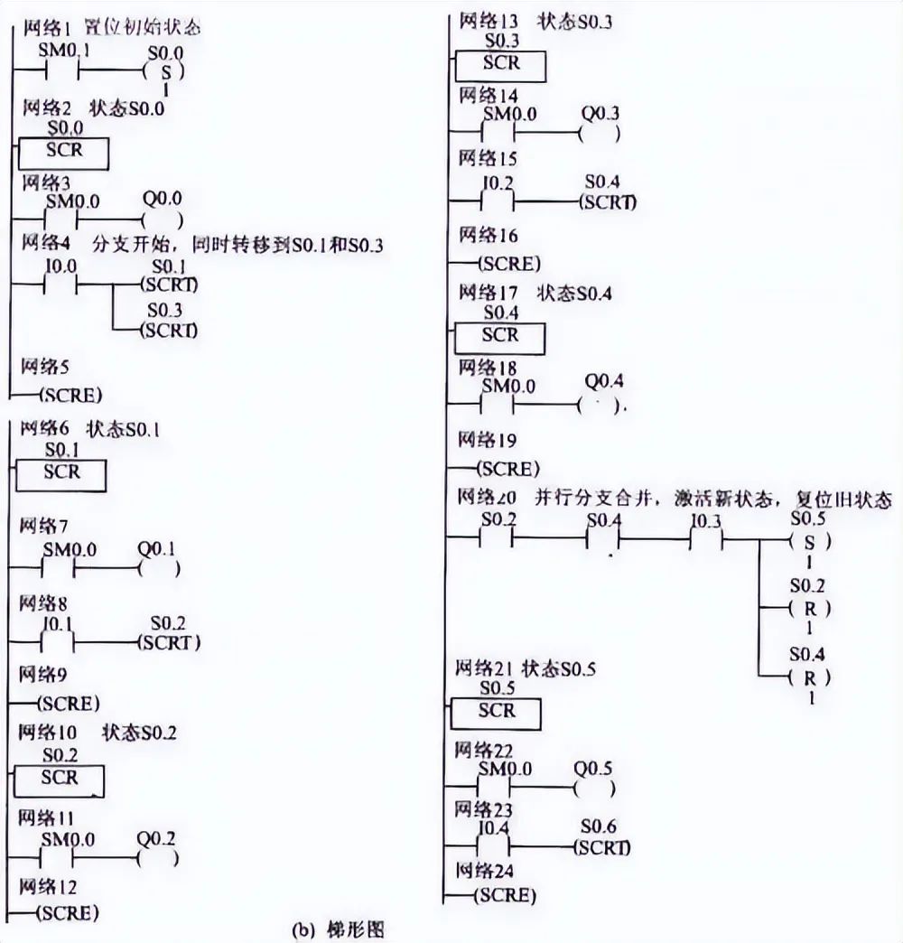
In many instances, a sequential control state flow must be divided into two or more different branches of control state flows, known as parallel branches. When a control state flow divides into multiple branches, all branch control state flows must be activated simultaneously. When the results of multiple control flows are the same, these control flows can be merged into one control flow, i.e., the connection of parallel branches. When merging control flows, all branch control flows must be completed. Thus, the next state can only transition when the transition condition is satisfied. Parallel sequences are generally represented by double horizontal lines, and the simultaneous ending of several sequences is also represented by double horizontal lines.
Source from the Internet; Disclaimer: Any works and images not sourced from this public account are cited from other sources for the purpose of conveying and sharing more information and do not represent this media’s endorsement of their views or responsibility for their authenticity; if there are copyright issues, please inform us immediately.
For more information and services, please follow “Automation Network www.ca800.com”