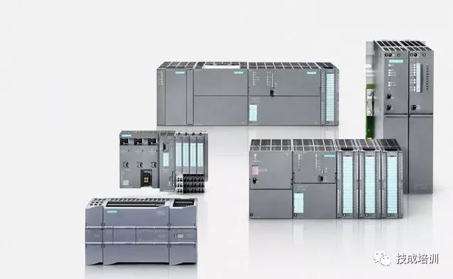

First, let’s understand what digital and analog signals are?Why do PLCs need to use analog signals?
Digital Signals
Digital signals are a type of physical quantity. Their changes are discontinuous over time, occurring only at a series of discrete moments. This type of physical quantity is called a digital signal. It refers to quantities that are dispersed and do not have intermediate values.
Analog Signals
Analog signals refer to quantities that change continuously within a certain range; that is, they can take any value within a defined range (domain).
Digital signals are discrete quantities, not continuous changing quantities, and can only take a few discrete values, such as binary digital variables that can only take two values.
For practical industrial applications, both digital and analog signals are essential.
In the automation control of factories, we need to monitor and control data such as temperature, pressure, liquid level, depth, etc.
For example, in controlling a boiler, we need the water to reach a certain temperature, which is generally adjustable, say 50 degrees Celsius or 70 degrees Celsius, and digital signals cannot meet these conditions.
Another example is that some chemical companies need to measure the acidity or alkalinity of liquids, which cannot be represented by digital signals of 0 or 1, but can only be represented by analog signals, such as pH 6.5, pH 7.0, etc., to clearly depict the actual data.
Learning about analog signals should actually cover two parts:
1. Hardware
Hardware includes selection and wiring. Selection refers to choosing different analog signals and PLCs for different working conditions, such as whether to use 0-10V, 4-20mA, 0-20mA, or special thermocouple signals.
Secondly, wiring should not be underestimated; different PLCs have different wiring methods.
For Siemens S7-300 series, we need to use expansion modules, open Siemens STEP7, select the appropriate PLC and analog modules, and add the modules.
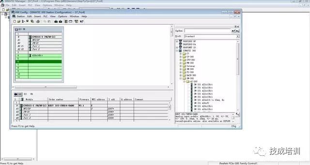
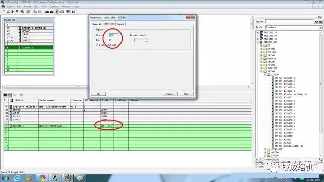
For PLCs, each analog signal has a fixed address, which can be recognized and calculated in the program; we need to find the appropriate address and add it.
According to the field equipment, select the appropriate range. If measuring temperature, a specific temperature module needs to be used, and the appropriate temperature signal must be selected. We have introduced temperature control in previous articles; those interested can look for it.
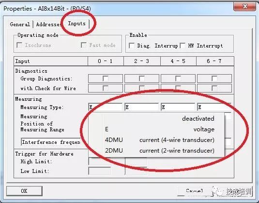
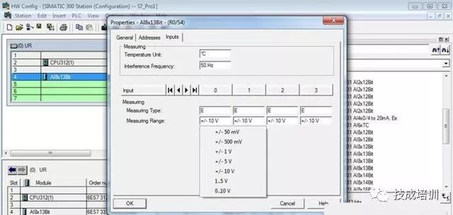
For voltage signals, there are various selectable types, which can be chosen according to the actual device’s signal type. For example, -10V to 10V, -5V to 5V, -1V to 1V, and 1-5V.
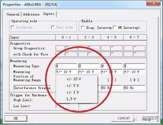
Of course, there are many analog expansion modules in the Siemens series, and in addition to those mentioned in the text, there are many other voltage signal applications in different fields, as shown in the figure below.
For current signals, they are divided into two-wire and four-wire systems, which need to be selected according to the actual instrument.
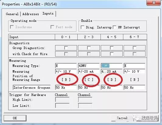
As shown in the figure above, after selecting the analog input type, you need to switch the hardware’s range card to the corresponding position.

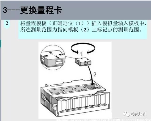
Remember to turn off the power before removing the module, and after adjustments, power it on and download the hardware configuration.
For other PLCs, there is no need for this step of changing the range card; just connect the wires directly to the PLC analog input module.
2. Software Programming
For those new to PLC programming, programming the analog input and output modules is much more difficult than general program control using bit variables, as it involves not only programming but also the derivation and use of conversion formulas for analog signals. Different sensors and transmitters convert through different analog input and output modules, and their conversion formulas are different. If the chosen conversion formula is incorrect, the program will definitely be wrong.
In fact, for PLCs, they can accept data ranging from -32767 to 32767, and we need to convert this data into the actual data we need.
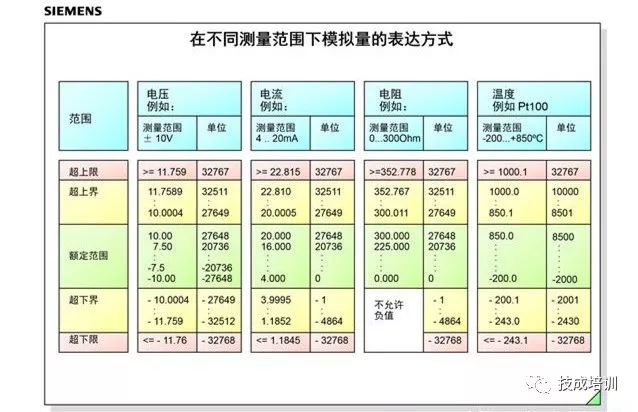
The following figure shows how to distinguish between current and voltage signals.
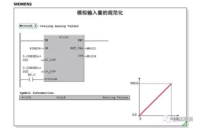
This means converting the data from analog channel 304 to actual data with a range of 0-500 and assigning it to MW104.
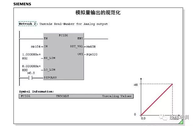
Analog output, on the other hand, converts data from MW104 to 0-100% analog data. For example, if the external signal PQW320 is 0-10V, it corresponds to 0V-10V.
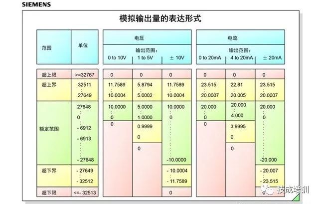
This figure is the representation of analog output; everyone can save it for reference.
Finally, here’s a simple example explanation:
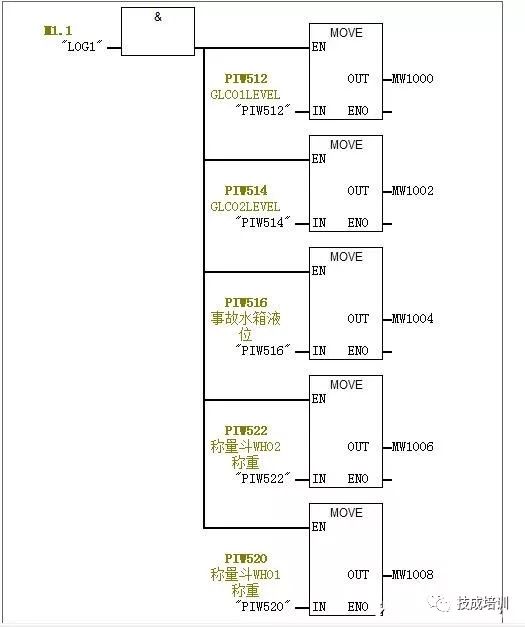
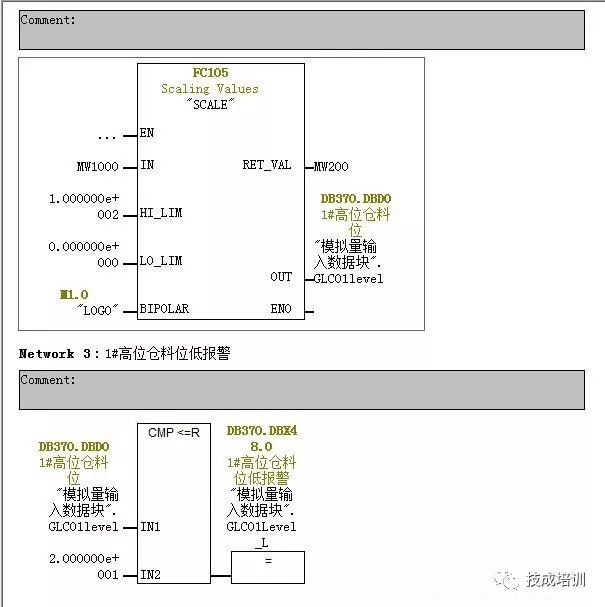
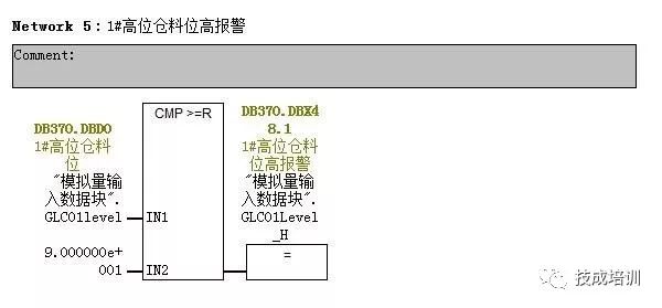
This is part of a not very complex material feeding program, which is easy to understand. It involves a radar level meter in a large material warehouse. The radar level meter in this project can detect raw material levels from 0.5 to 10 meters. Due to production reasons, this warehouse needs to ensure that there is always raw material.
Therefore, we need to replenish materials when the level in the warehouse drops below about 2 meters to ensure sufficient raw materials, and stop when it reaches 9 meters to avoid piling up outside.
So, do you understand analog input and output now?

 Click here if you like
 Learn PLC and Electrical Courses for Free, click to read the original text