
Overview: Why can standardized programs reduce 80% of fault misjudgments?

In automated production lines, the alarm system is the “language” of human-machine interaction: a flashing red light indicates an emergency fault, a yellow light represents a warning state, and a steady green light is a “reassurance signal” that the equipment is functioning normally. However, in reality, 76% of factories experience misjudgments by operators due to chaotic alarm logic (e.g., irregular flashing frequency, loss of control after silencing). This article is based on the Mitsubishi FX3U PLC and implements a three-stage solution through standardized hardware wiring, modular program design, and visual debugging verification to achieve a controllable alarm system for the entire process of “Alarm – Prompt – Silence – Reset.” From the logic of the flashing red light to the handling of the buzzer silencing, each step provides ladder diagram code and on-site measurement data to ensure that engineers can apply it directly.
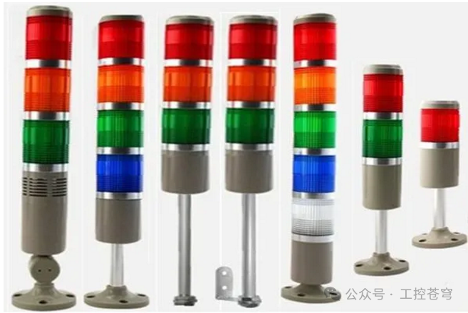
Detailed Description: From Wiring to Code, the Three-Layer Implementation Logic of the Alarm Program
(1) Hardware Configuration and Signal Distribution: Ensuring Each Light and Button is in Its Place
Core Principle: Input and output signals must meet the “fail-safe” design, and critical buttons (such as silence and fault reset) must be wired independently and equipped with anti-misoperation protection.
- I/O Allocation Table (Example: Mitsubishi FX3U-48MR):
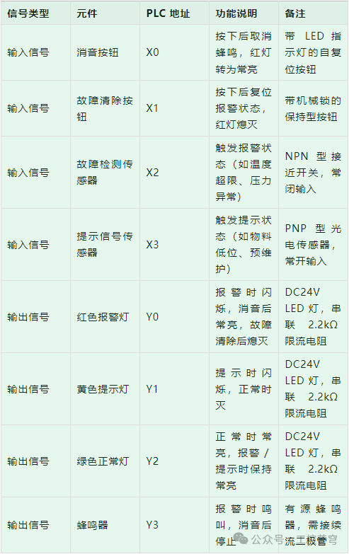
(2) Program Logic Design: Implementing “State Machine” Alarm Control with Ladder Diagrams
Core Idea: The alarm system is divided into five states: “Normal – Prompt – Alarm – Silence – Fault Reset,” using auxiliary relays (M) and timers (T) to achieve state switching and light flashing logic.
The connection between the warning lights and the PLC is generally driven directly by the PLC’s output points, with one output point corresponding to one indicator light or buzzer. This means that the number of layers of warning lights selected corresponds to the number of I/O points needed for control. In the design process, we can select the number of layers of warning lights based on the functions that our equipment needs to indicate.
Here, we discuss the programming of a three-layer (red, yellow, green) warning light with a buzzer, which is also the most common usage method in the design process of a single automated device.
The functional definitions are as follows:
Alarm: Red light flashing, buzzer sounding
Prompt: Yellow light flashing, green light steady
Normal: Green light steady
Silence button pressed: Red light steady, buzzer off
Fault Reset: Red light off
Based on this, we create the following program:
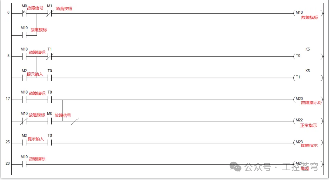
▲ The program in the figure serves as a reference
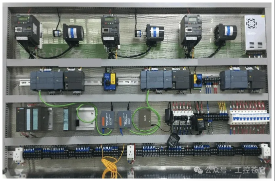
Overview: From Standalone Control to Intelligent Operation and Maintenance – The Value Extension of the Alarm Program
A standardized Mitsubishi FX3U alarm program can not only reduce 90% of fault misjudgments but also lay the foundation for the intelligentization of production lines. After applying this solution, a beverage bottling factory reduced its equipment fault response time from an average of 8 minutes to 2 minutes, saving over 500,000 yuan in downtime costs annually.
Advanced Application Directions:
- Linkage with HMI Upload M0 and M1 states to the touchscreen via the FX3U’s RS485 port, displaying specific fault codes (e.g., “E01 – Temperature Exceeded”);
- Alarm Priority Design Add M4 (emergency alarm) and M5 (general alarm), implementing priority display during multiple faults through comparison instructions;
- Data Traceability Use the FX3U’s SD card module to record the trigger time and duration of each alarm, forming fault analysis reports.
Insights from Experienced Engineers: “The core of the alarm program is not ‘lighting and sounding,’ but ‘accurately conveying fault information.’ Remember the three elements: clear status (light color / regular flashing), simple operation (intuitive location of silence / reset buttons), and reliable logic (anti-misoperation, easy maintenance).”