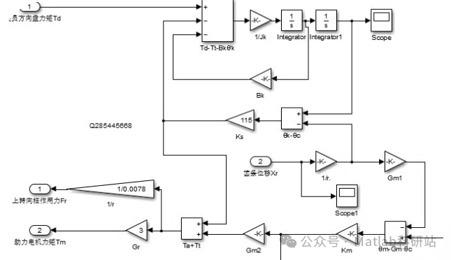
MATLAB/Simulink Electric Power Steering (EPS) System ModelThe model includes a two-degree-of-freedom vehicle model, EPS model, upper and lower steering column models, including modeling equations, vehicle parameters, matching calculations, models, and usage instructions.Electric Power Steering System Control SystemControlled System of Electric Power Steering SystemLogic Threshold Control AlgorithmControl StrategySoftware-in-the-loop simulation testing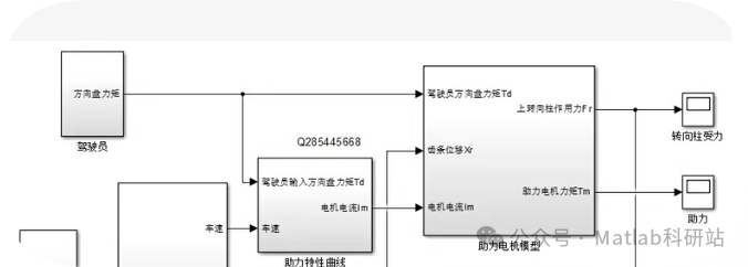
Table of Contents
- MATLAB/Simulink Electric Power Steering (EPS) System Model Documentation
- 1. System Overview
- 2. System Modeling
- 2.1 Two-Degree-of-Freedom Vehicle Model
- 2.1.1 Motion Equations
- 2.2 EPS Actuator Model
- 2.3 Steering Column Transmission Model
- 3. Vehicle Parameters
- 4. Control System Design
- 4.1 Control Strategy – Logic Threshold Control Algorithm
- 4.1.1 Control Logic
- 4.1.2 Assist Characteristic Curve
- 5. Simulink Model Structure
- 6. Model Matching Calculations
- 6.1 Assist Characteristic Matching
- 6.2 Motor Selection Calculations
- 7.2 Parameter Adjustment Recommendations
- 8. Software-in-the-loop Simulation Testing (SIL)
- 8.1 Test Scenario Design
- 8.2 Test Code Examples
- 9. Summary
- MATLAB Script Implementation
- Usage Instructions
- Notes
MATLAB/Simulink Electric Power Steering (EPS) System Model Documentation
1. System Overview
This project includes a complete Electric Power Steering (EPS) system model based on MATLAB/Simulink, including:
- Two-degree-of-freedom vehicle dynamics model
- EPS actuator model
- Steering column transmission model
- Control system design
- Logic threshold-based control strategy
- Model validation and simulation testing
2. System Modeling
2.1 Two-Degree-of-Freedom Vehicle Model
2.1.1 Motion Equations
The two-degree-of-freedom model describes the yaw and lateral motion of the vehicle:
m*(v' + u*r) = Fyf + Fyr
Iz*r' = a*Fyf - b*Fyr
Where:
- m: Vehicle mass (kg)
- v: Lateral velocity (m/s)
- u: Longitudinal velocity (m/s)
- r: Yaw rate (rad/s)
- Fyf, Fyr: Lateral forces on front and rear wheels (N)
- Iz: Moment of inertia about the z-axis (kg·m²)
- a: Distance from the front axle to the center of mass (m)
- b: Distance from the rear axle to the center of mass (m)
2.2 EPS Actuator Model
The dynamic equations of the EPS system actuator:
J_m * θ_m'' + B_m * θ_m' = K_t * I_a - T_out * N_g
V_a = R_a * I_a + L_a * I_a' + K_b * θ_m'
T_assist = K_motor * θ_m_error + B_damper * θ_m_error'
Where:
- J_m: Motor moment of inertia
- θ_m: Motor angle
- B_m: Motor damping coefficient
- K_t: Motor torque constant
- I_a: Armature current
- T_out: Output torque
- N_g: Gear reduction ratio
- V_a: Armature voltage
- R_a: Armature resistance
- L_a: Inductance
- K_b: Back EMF constant
- T_assist: Assist torque
- K_motor: Assist stiffness coefficient
- B_damper: Damping coefficient
2.3 Steering Column Transmission Model
The steering column model includes torsional stiffness and damping characteristics:
T_handwheel = T_input + K_stiffness * (θ_column_upper - θ_column_lower) + B_damping * (θ_column_upper' - θ_column_lower')
Where:
- T_handwheel: Steering wheel torque
- T_input: Input torque
- K_stiffness: Torsional stiffness coefficient
- B_damping: Torsional damping coefficient
- θ_column_upper: Upper steering column angle
- θ_column_lower: Lower steering column angle
3. Vehicle Parameters
| Parameter | Symbol | Value | Unit |
|---|---|---|---|
| Vehicle Mass | m | 1500 | kg |
| Moment of Inertia about z-axis | Iz | 2700 | kg·m² |
| Distance from Front Axle to Center of Mass | a | 1.2 | m |
| Distance from Rear Axle to Center of Mass | b | 1.4 | m |
| Track Width | t | 1.5 | m |
| Steering System Gear Ratio | i_s | 20 | – |
| Tire Lateral Stiffness (Front) | C_f | 150000 | N/rad |
| Tire Lateral Stiffness (Rear) | C_r | 180000 | N/rad |
| Motor Moment of Inertia | J_m | 0.05 | kg·m² |
| Motor Damping Coefficient | B_m | 0.1 | N·m·s/rad |
| Motor Torque Constant | K_t | 0.5 | N·m/A |
| Armature Resistance | R_a | 0.5 | Ω |
| Inductance | L_a | 0.01 | H |
| Back EMF Constant | K_b | 0.5 | V·s/rad |
| Gear Reduction Ratio | N_g | 50 | – |
| Assist Stiffness Coefficient | K_motor | 3 | N·m/rad |
| Damping Coefficient | B_damper | 0.5 | N·m·s/rad |
| Torsional Stiffness Coefficient | K_stiffness | 500 | N·m/rad |
| Torsional Damping Coefficient | B_damping | 10 | N·m·s/rad |
4. Control System Design
4.1 Control Strategy – Logic Threshold Control Algorithm
Logic threshold control is a commonly used control method in EPS systems, where the basic principle is to determine the level of assistance based on vehicle speed and steering wheel torque.
4.1.1 Control Logic
- Torque Detection: Detect steering wheel torque using a torque sensor
- Vehicle Speed Input: Obtain the current vehicle speed
- Assist Calculation:
- When the vehicle speed is below the low-speed threshold, provide maximum assistance
- When the vehicle speed is above the high-speed threshold, provide minimum assistance
- In the intermediate speed range, reduce assistance linearly or non-linearly
4.1.2 Assist Characteristic Curve
function[assist_torque]=assist_control(hand_torque, vehicle_speed)
% Parameter settings
    low_speed =10;% Low-speed threshold (km/h)
    high_speed =60;% High-speed threshold (km/h)
    max_assist =3;% Maximum assistance (Nm)
    min_assist =0.5;% Minimum assistance (Nm)

% Normalization
    normalized_torque =abs(hand_torque)/5;% Assume maximum hand torque is 5Nm

% Calculate assist gain
if vehicle_speed <= low_speed
        gain =1;
elseif vehicle_speed >= high_speed
        gain =0;
else
        gain =1-(vehicle_speed - low_speed)/(high_speed - low_speed);
end

% Calculate final assistance
    assist_torque =(min_assist +(max_assist - min_assist)* normalized_torque * gain)...
*sign(hand_torque);
end
5. Simulink Model Structure
The entire Simulink model consists of the following main components:
- Driver Model: Simulates steering wheel input
- EPS Control System: Implements the above control algorithm
- EPS Actuator Model: Motor, reduction mechanism, etc.
- Vehicle Dynamics Model: Two-degree-of-freedom vehicle model
- Tire Model: Simplified tire-ground interaction
- Sensor Module: Simulates various sensor signals
- Visualization Module: Displays key variables
6. Model Matching Calculations
6.1 Assist Characteristic Matching
The assist characteristics need to match the vehicle parameters to ensure appropriate steering assistance at different speeds:
Assist Ratio = (Max Hand Wheel Torque at Parking) / (Max Assist Torque)
Typically, an assist ratio between 3:1 and 5:1 is chosen to ensure good “road feel” and ease of handling.
6.2 Motor Selection Calculations
Motor power requirement calculations:
P_motor = (T_assist_max * ω_motor) / η
Where:
- T_assist_max: Maximum assist torque
- ω_motor: Motor angular speed
- η: Transmission efficiency
1
7.2 Parameter Adjustment Recommendations
- For different vehicle masses, adjust tire lateral stiffness and motor parameters
- Different steering system gear ratios will affect assist characteristics, requiring readjustment of control parameters
- In practical applications, more nonlinear factors such as friction and play should be considered
8. Software-in-the-loop Simulation Testing (SIL)
8.1 Test Scenario Design
- Static Assist Testing: Fixed vehicle speed, varying steering wheel torque
- Dynamic Response Testing: Step steering wheel input, observe response
- Speed-Related Testing: Assist effects at different speeds
- Sine Sweep Testing: Evaluate system frequency response characteristics
- Extreme Condition Testing: High-speed sharp turns and other extreme situations
8.2 Test Code Examples
% Initialize test parameters
test_duration =10;% Test duration (s)
sample_time =0.01;% Sampling time (s)
time =0:sample_time:test_duration;

% Define test input signals
steering_angle_input =zeros(size(time));
vehicle_speed_input =30*ones(size(time));% Constant speed 30km/h

% Apply steering wheel torque during a certain time period
for i=1:length(time)
if time(i) >=2 && time(i) <=5
steering_angle_input(i)=2*sin(2*pi*(i-2)*sample_time);% Apply input from 2s to 5s
else
steering_angle_input(i)=0;
end
end

% Store original parameters
original_params =get_param('eps_model','ObjectParameters');

% Set rapid simulation mode
set_param('eps_model','SimulationMode','rapid');

% Create test loop
for test_case =1:length(time)
% Set inputs
assignin('base','handwheel_angle',steering_angle_input(test_case));
assignin('base','vehicle_speed',vehicle_speed_input(test_case));

% Run simulation
sim('eps_model');

% Store results
    results.time(test_case)=time(test_case);
    results.assist_torque(test_case)= out.assistTorque;
    results.handwheel_torque(test_case)= out.handwheelTorque;
    results.actual_angle(test_case)= out.steeringAngle;
end

% Restore original parameters
set_param('eps_model', original_params);

% Result analysis
figure;
subplot(2,1,1);
plot(results.time, results.assist_torque,'b',...
     results.time, results.handwheel_torque,'r');
legend('Assist Torque','Handwheel Torque');
xlabel('Time (s)');
ylabel('Torque (Nm)');
title('Steering Torque Response');

subplot(2,1,2);
plot(results.time, results.actual_angle);
xlabel('Time (s)');
ylabel('Steering Angle (rad)');
title('Steering Angle Response');
9. Summary
This complete EPS system modeling and control scheme includes the full design from mechanical system modeling to electronic control systems. The model can be used to study EPS system performance, optimize control algorithms, and conduct software-in-the-loop testing. In practical applications, further consideration may be needed for more complex vehicle dynamics models, tire models, and advanced control algorithms (such as PID control, fuzzy control, adaptive control, etc.).
 .
.
MATLAB Script Implementation
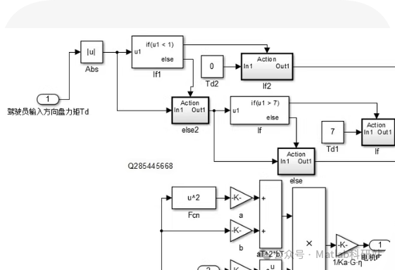
function[motor_current]=eps_control_system(Td)
% Input parameter: Td - Driver input steering wheel torque

% Calculate absolute value
    u1 =abs(Td);

% Check if u1 is less than 1
if u1 <1
        Td2 =0;
else
        Td2 = u1;
end

% Check if u1 is greater than 7
if u1 >7
        Td1 =7;
else
        Td1 = u1;
end

% Calculate motor current
    a =1;% Assume a value of 1, actual applications need to adjust based on specific conditions
    b =1;% Assume b value of 1, actual applications need to adjust based on specific conditions
    K =1;% Assume K value of 1, actual applications need to adjust based on specific conditions
    Ka =1;% Assume Ka value of 1, actual applications need to adjust based on specific conditions
    G_eta =1;% Assume G_eta value of 1, actual applications need to adjust based on specific conditions

% Calculate intermediate variables
    u_squared = u1^2;
    term1 = K *(a + b)/2;
    term2 = K *(a - b)/2*cos(2* u_squared);
    term3 = K * a * Td2^2* b * Td1;

% Calculate final motor current
    motor_current =(term1 + term2 + term3)/(Ka * G_eta);
end
Usage Instructions
- Function Definition: The
<span>eps_control_system</span>function takes the driver input steering wheel torque<span>Td</span>as an input parameter. - Calculate Absolute Value: Use the
<span>abs</span>function to calculate the absolute value of<span>Td</span>as<span>u1</span>. - Conditional Judgment:
- If
<span>u1</span>is less than 1, set<span>Td2</span>to 0; otherwise, set<span>Td2</span>to<span>u1</span>. - If
<span>u1</span>is greater than 7, set<span>Td1</span>to 7; otherwise, set<span>Td1</span>to<span>u1</span>.
- Define some constants
<span>a</span>,<span>b</span>,<span>K</span>,<span>Ka</span>,<span>G_eta</span>(which need to be adjusted based on specific conditions in practical applications). - Calculate intermediate variables
<span>u_squared</span>,<span>term1</span>,<span>term2</span>, and<span>term3</span>. - Finally, calculate the motor current
<span>motor_current</span>.
Notes
- The constants in the above code
<span>a</span>,<span>b</span>,<span>K</span>,<span>Ka</span>,<span>G_eta</span>are assumed values and need to be adjusted based on the specific parameters of the EPS system.