 When it comes to PID tuning, it can be overwhelming, and it’s easy to crash after adjusting for a long time! Ordinary air conditioning water temperature control doesn’t need to be this complicated. By using “upper and lower limit thresholds + logical linkage,” we can directly replace PID. In just 4 steps, we can achieve water temperature regulation + fan coordination without complex algorithms, and it can be implemented in half an hour, maximizing practicality!
1. Water Temperature Coordination Control Requirements
1. Temperature Acquisition: The PLC automatically obtains the analog signal from the PT100 sensor and converts it into the actual water temperature value;
2. Interval Temperature Control: Pre-set a comfortable range; automatically cool down if above the upper limit, and heat up if below the lower limit;
3. Fan Coordination: Control the fan speed based on the water temperature status to avoid frequent start-stop cycles;
4. Mode Switching: Supports manual/automatic seamless switching, with emergency stop signals taking priority to ensure operational safety;
5. Status Self-Locking: Once the temperature control status is triggered, it remains locked, and power loss and restart do not invalidate it.
2. Data Block Definition
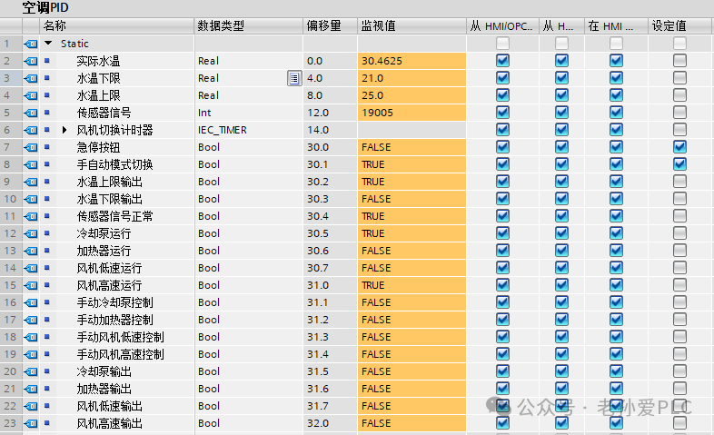 3. 4 Steps to Write the Water Temperature Coordination Program
Step 1: Temperature Acquisition and Signal Conversion
Core Logic: Read the raw signal from the sensor, convert it to the actual water temperature using standard instructions, and store it in the corresponding data point.
Operation Steps:
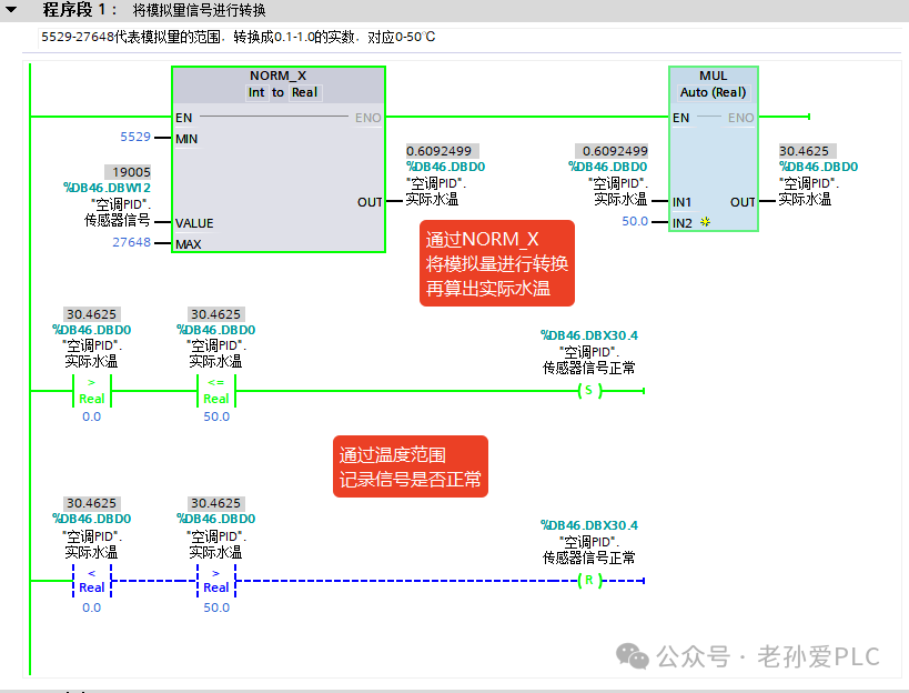
1. Call the NORM_X instruction, set the enable bit (EN) to 1, parameter settings: MN=5529, MAX=27648, VALUE=DBW12 (sensor signal), OUT=DBD0 (actual water temperature);
2. Call the MUL instruction, set the enable bit (EN) to 1, parameter settings: IN1=DBD0 (actual water temperature), IN2=50.0, OUT=DBD0 (final 0-50℃ water temperature);
3. Add signal verification: When DBD0 is between 0-50℃, set DBX30.4 (sensor signal normal), otherwise reset.
Step 2: Water Temperature Interval Judgment Logic
Core Logic: Compare the actual water temperature with the preset upper and lower limits to automatically trigger the corresponding state, providing a basis for device control.
Operation Steps:
1. Trigger Conditions: DBX30.1 (automatic mode) = 1, DBX30.4 (signal normal) = 1, DBX30.0 (emergency stop normally closed) in series;2. Above Upper Limit: DBD0 > DBD8 (25.0℃), set DBX30.2, reset DBX30.3;3. Below Lower Limit: DBD0 < DBD4 (21.0℃),set DBX30.3, reset DBX30.2;4. Within Interval: DBD4 ≤ DBD0 ≤ DBD8, simultaneously reset DBX30.2, DBX30.3.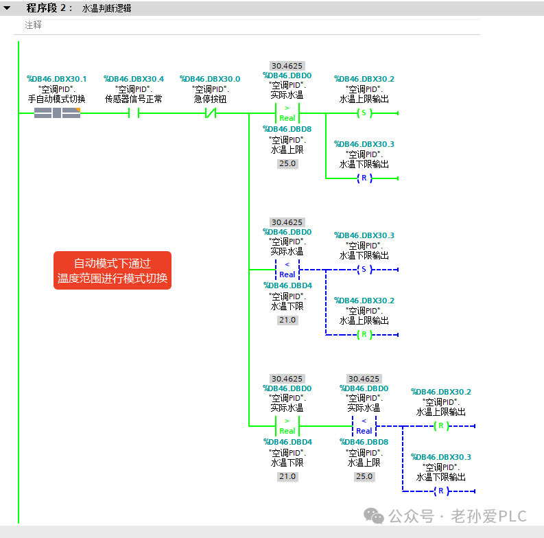
Step 3: Fan and Cooling/Heating Coordination
Core Logic: Once the state is triggered, directly control the corresponding output points to drive the device for precise temperature control.
Operation Steps:
1. Above Upper Limit (DBX30.2=1): Set DBX30.5 (cooling pump), DBX31.0 (fan high speed), reset DBX30.6 (heater), DBX30.7 (fan low speed), call DBX14.0 (delay);2. Below Lower Limit (DBX30.3=1):In series with DBX14.0 normally closed point, set DBX30.6 (heater), DBX30.7 (fan low speed), reset DBX30.5 (cooling pump), DBX31.0 (fan high speed);3. Within Interval (DBX30.2=0 and DBX30.3=0): Set DBX30.7 (fan low speed), reset DBX30.5, DBX30.6, DBX31.0.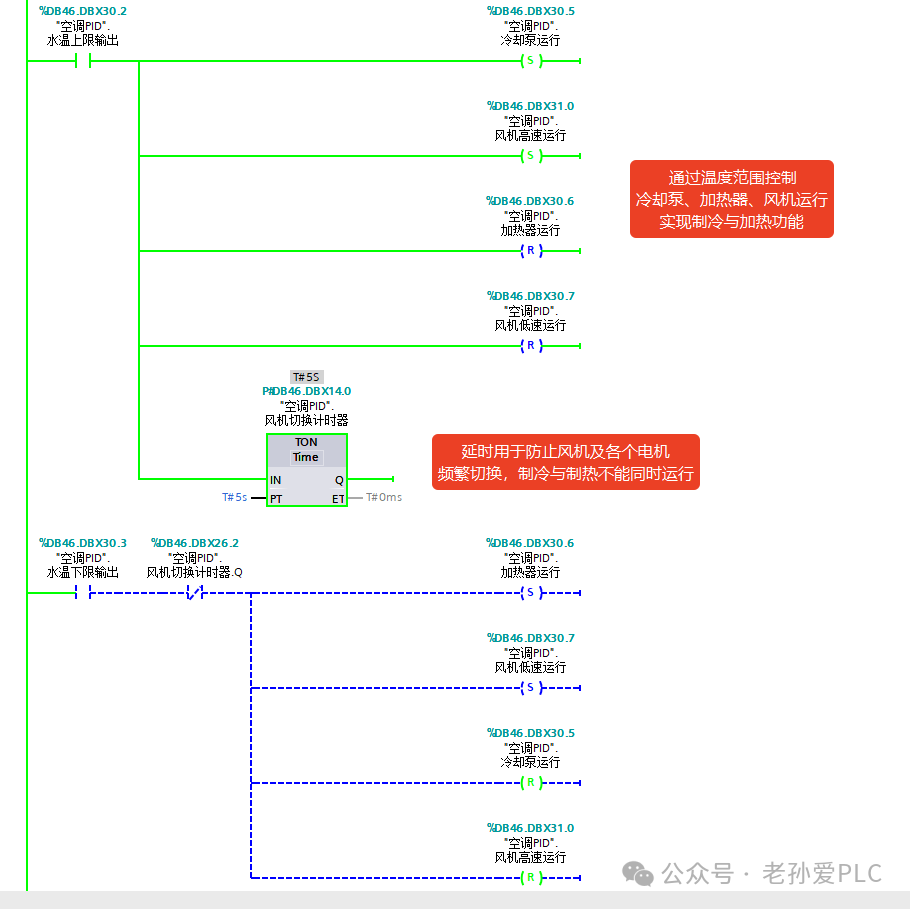
Step 4: Manual/Automatic Mode Switching
Core Logic: The automatic mode allows the output points to operate independently, while the manual mode directly controls the device, with interlocks to prevent conflicts.
Operation Steps:
1. Automatic Mode (DBX30.1=1): DBX30.5 controls DBX31.5, DBX30.6 controls DBX31.5, DBX30.7 controls DBX31.7, DBX31.0 controls DBX32.0;2. Manual Mode (DBX30.1=0): DBX32.0 controls DBX33.0, DBX32.1 controls DBX33.1, DBX32.2 controls DBX33.2, DBX32.3 controls DBX33.3;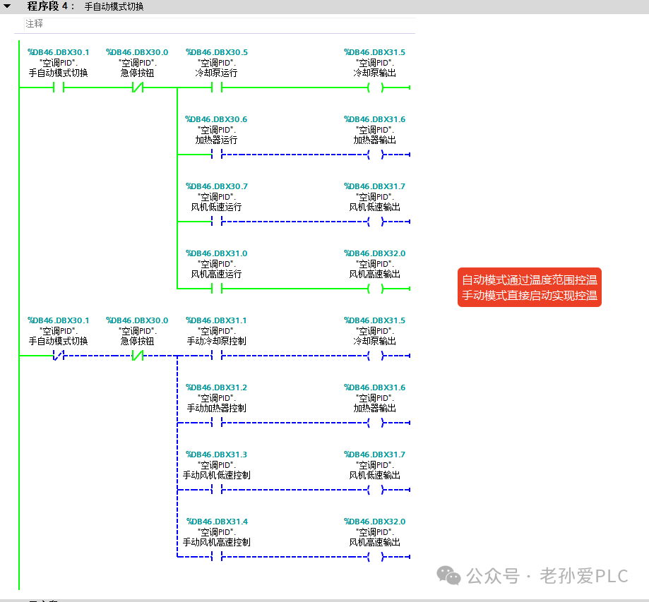
4. Core Logic of Water Temperature Coordination (Beginners Only Need to Remember 2 Points)
1. Simplifying Logic is Key: No need for PID or complex algorithms; precise temperature control can be achieved through “interval judgment + device coordination”. There’s no need to get bogged down in theory; just follow the steps to implement it;
2. Prioritize Practicality to Avoid Pitfalls: First, ensure device interlocks (cooling/heating, fan high/low speed do not conflict), then add a delay protection. This can help avoid 80% of faults during on-site operation, making maintenance easier.
Learn technology solidly, improve a little every day! Do your best to help more people!