Task Description
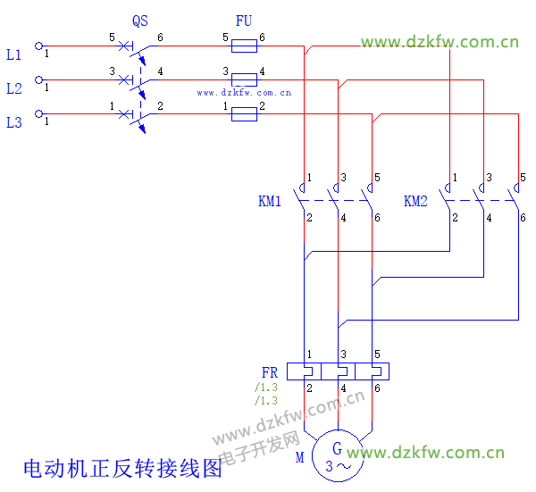
Based on the circuit diagram below, design a forward and reverse control for the motor using Mitsubishi PLC. Identify all input and output quantities, allocate I/O addresses, draw the I/O wiring diagram, and write the PLC program!
I/O Address Allocation
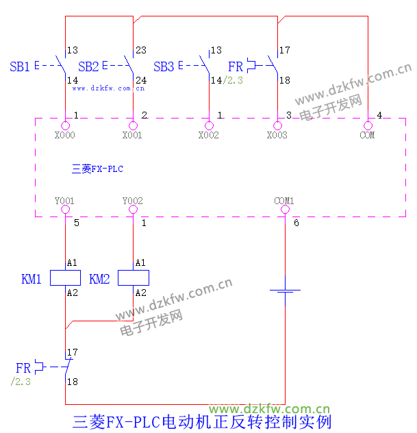
According to the task requirements, this circuit needs to switch between forward and reverse. There are two contactors in the problem, resulting in two output quantities: KM1 for forward operation Y001 and KM2 for reverse operation Y002, which control the motor’s forward and reverse respectively.
Three buttons are needed for control: the forward control button X001, the reverse control button X002, and the stop button X000, along with the overload protection of the thermal relay FRX003, thus requiring four input quantities.
I/O Wiring Diagram
Program
Program Analysis
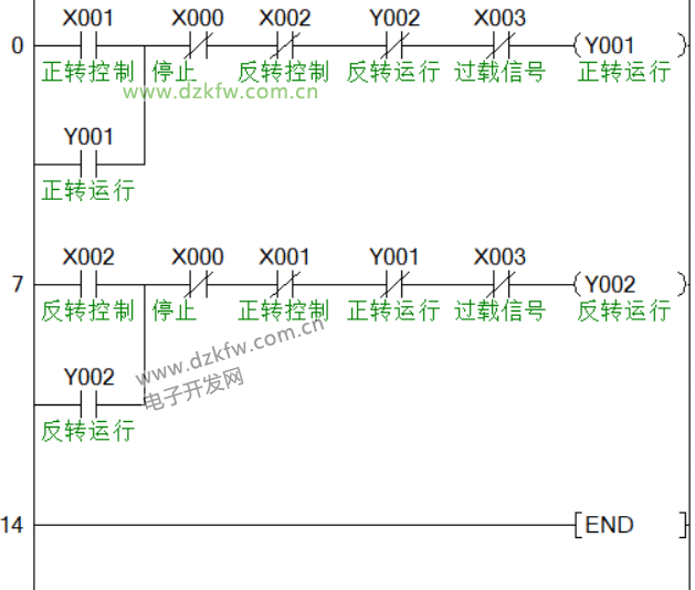
When the forward control button X001 is pressed, Y001 is energized and self-locks, causing the motor to start running forward. When the reverse control button X002 is pressed, Y001 is de-energized, Y002 is energized and self-locks, causing the motor to start running in reverse. When the stop button X000 is pressed, both Y001 and Y002 are de-energized, stopping the motor. If the thermal relay overload activates, both Y001 and Y002 are de-energized, stopping the motor.