In the previous issue, we outlined the common industrial control devices and software systems in Industrial Control Systems (ICS). Today, we will explore the communication protocols between devices and software systems. Before we begin, let’s first understand the topological access relationship between control devices and software: refer to the hierarchical model division of IEC62264-1:
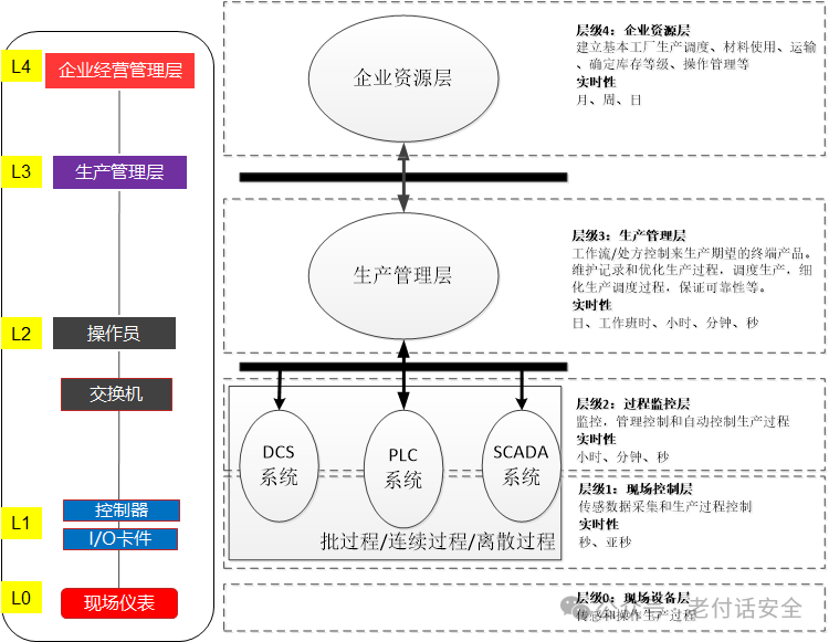
L4 Enterprise Resource Layer: Mainly includes ERP system functional units, used to provide decision-making tools for enterprise decision-makers;
L3 Production Management Layer: Mainly includes MES system functional units, used for managing the production process, such as manufacturing data management, production scheduling management, etc.;
L2 Process Monitoring Layer: Mainly includes monitoring servers and HMI system functional units, used for collecting and monitoring production process data, and utilizing HMI systems for human-machine interaction;
L1 Field Control Layer: Mainly includes various types of controller units, such as PLCs, DCS control units, etc., used to control various execution devices;
L0 Field Device Layer: Mainly includes various process sensing devices and execution device units, used for sensing and operating the production process.
Next, we will understand how they communicate at each level.
Communication between L0 and L1 layer devices
Communication methods between L0 and L1 layer devices
L0 layer sensors and instrument valves are connected to L1 layer I/O cards via hardwired RS485 cables. The I/O cards interconnect with the CPU of the PLC or the controller of the DCS. This part generally transmits data and commands through electrical signals, mainly using protocols such as Modbus and PROFIBUS. This is not within the scope of industrial control security research, so we will not elaborate further. However, from the perspective of industry development, traditional field buses (such as PROFIBUS) are migrating towards industrial Ethernet (such as PROFINET, EtherCAT, EtherNet/IP), and OPC UA is becoming a key enabling technology for achieving vertical integration and Industry 4.0.
Extension: PROFINET, developed by Siemens in collaboration with several automation giants, has made breakthroughs in field buses for manufacturing (PROFIBUS-DP) and process industries (PROFIBUS-PA), enabling data transmission over Ethernet links. PROFINET defines three different communication channels:
-
TCP/IP Channel:
-
Used for: Non-real-time data exchange, such as device configuration, parameter settings, and diagnostic information reading.
-
Features: Uses standard Ethernet stack, seamlessly integrates with IT networks. This is the basis for its “backward compatibility” with office Ethernet.
-
RT (Real-Time) Channel:
-
Used for: Process data exchange at the factory automation level, such as communication between PLC and I/O modules.
-
Features: Reduces latency by optimizing the Ethernet stack, bypassing the TCP/IP stack, meeting the real-time requirements of most automation applications (cycle time ~10ms).
-
IRT (Isochronous Real-Time) Channel:
-
Used for: High-performance motion control applications requiring high synchronization and deterministic delay, such as multi-axis CNC machines and printing machinery.
-
Features: Implements time-slicing mechanisms at the hardware (ASIC/switch chip) level, reserving dedicated bandwidth for real-time data, ensuring extremely low jitter and nanosecond-level synchronization accuracy (cycle time <1ms).
Communication between L1 layer devices and L2 layer devices and between L1 layer devices
L1 layer devices mainly include PLCs, controllers, etc. In the continuous control process of a large factory, a master PLC connects multiple slave PLCs. For example, in a large water treatment plant: the master PLC is located in the central control room. Slave PLC#1 is located in the water pump room, controlling the pumps and grating machines. Slave PLC#2 is located in the sedimentation tank, controlling the sludge scraper valve. Slave PLC#3 is located in the dosing room, controlling the chemical dosing. These PLCs use different protocols depending on the manufacturer, with popular ones being PROFINET (Siemens), EtherNet/IP (Rockwell), EtherCAT (Beckhoff), and the general Modbus TCP/IP protocol, interconnected using industrial Ethernet.
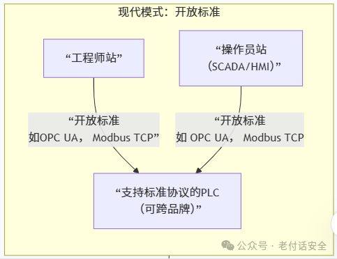
L2 layer devices mainly include operator stations and engineer stations. The operator station mainly installs SCADA software for monitoring the operational status of PLCs. When the PLC operation deviates from the original track, the operator will manually correct it in the SCADA software. The engineer station is only used at the beginning of the production project process to set the execution logic of the PLC through programming software. When the PLC operates normally, the engineer station is not in use. Unless the engineering logic needs to change, it will be modified again through programming software. The communication protocols used between them are varied:
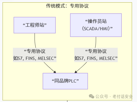
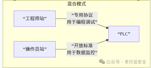
Traditional dedicated protocols include: S7 (the main communication method between Siemens TIA Portal software and PLC), CIP (Rockwell, some devices are configured, programmed, and modified online via EtherNet/IP), Modbus (owned by Schneider), FINS (Omron), MELSEC (Mitsubishi), etc.
With technological advancements, to break brand barriers and achieve system interoperability, Ethernet-based open standard protocols have become the absolute mainstream. Common protocols include:
OPC UA – The king of standards (PLC acts as an OPC UA server, exposing its internal data (such as data blocks, tags) in a standardized “information model”. The operator station (SCADA) and engineer station act as OPC UA clients, connecting to the PLC OPC UA server via TCP/IP network to read and write data.)
Modbus TCP/IP – The universal language (PLC has a built-in Modbus TCP server. SCADA/HMI (i.e., operator station) acts as a client, directly reading and writing its holding registers and coils by accessing the PLC’s IP address and port 502.)
General industrial Ethernet protocols such as PROFINET and EtherNet/IP. They are not only field buses but are also commonly used to connect upper-level systems. The network cards of operator stations and engineer stations need to support these protocols (usually requiring the installation of dedicated network card drivers). SCADA/HMI software can directly communicate with PLCs through these protocols, accessing their tags without going through OPC UA or Modbus TCP conversion, resulting in higher performance.
L2 layer devices and L3 layer devices interoperability
L2 layer devices mainly consist of engineer stations and operator stations, while L3 layer devices include MES servers, real-time database servers, historical database servers, and other advanced application servers. There are several modes for MES to communicate with production site devices:
Mode 1: Through upper computer/configuration software (SCADA) as an intermediary
Communication path:
<span>MES <--> Upper Computer/SCADA <--> PLC</span>
-
PLC: Responsible for the real-time control of lower-level devices, focusing on “how to do it”. It collects device status, sensor data, production output, fault codes, etc., and executes control commands from SCADA.
-
Upper Computer/SCADA: Acts as a human-machine interface and data concentrator. It collects, stores, processes, and displays real-time data from multiple PLCs, providing operators with a visual interface. At the same time, it also serves as a historical database.
-
MES: Responsible for production management, focusing on “what to do”. It receives production orders from ERP, transforms them into detailed work instructions (e.g., what product to produce, what the formula is, in what order), and tracks the execution progress of orders, material consumption, equipment efficiency, etc.
-
Example of data flow:
-
MES system issues a command for “Production Order A, Quantity 100” to SCADA.
-
After receiving the command, SCADA breaks it down and issues it to the corresponding master PLC (e.g., setting recipe parameters, starting the production line).
-
The master PLC controls the production line to complete production and uploads real-time output and status information to SCADA.
-
SCADA continuously aggregates data, and when the output reaches 100, it notifies the PLC to stop and reports the “Order Completed” status back to the MES system.
In the early days, MES and PLC communication capabilities were weak, requiring SCADA as a bridge. SCADA handles high-frequency real-time data, while MES processes low-frequency management data, with clear responsibilities. SCADA can act as a firewall, preventing MES from directly accessing sensitive real-time control layers.
Mode 2: Direct communication between MES and PLC
Communication path:
<span>MES <--> PLC</span>
-
PLC: On the basis of existing real-time control functions, adds an interface for direct dialogue with upper-level systems. It needs to be able to understand and respond to MES commands.
-
MES: Directly “shakes hands” with the control system, reducing intermediate links.
-
How to achieve it?
-
Standard industrial protocols: Modern PLCs support Ethernet communication. MES systems can directly connect with PLCs using protocols such as OPC UA (preferred), Modbus TCP/IP, PROFINET, or EtherNet/IP.
-
Data mapping: PLC programmers will open a specific data area (e.g., DB block) in the PLC specifically for exchanging data with MES. The MES system directly reads and writes these addresses.
-
Example of data flow:
-
MES directly connects to the main PLC’s OPC UA server via the OPC UA client.
-
MES writes “Order Information” and “Start Command” directly into a data block of the PLC.
-
PLC executes production and writes “Current Output”, “Device Status”, “Material Code”, etc., directly into another data block.
-
MES directly reads information from these data blocks, monitoring order progress in real-time.
Is this the trend for the future?
-
Reducing latency: Eliminates the intermediate link of SCADA, making data exchange more direct and faster.
-
Reducing complexity: The system architecture becomes flatter, reducing the middleware and interfaces that need to be maintained.
-
Information fidelity: Avoids potential data conversion or loss at SCADA, ensuring consistency of data from the control layer to the management layer.
-
Cost-effectiveness: In some scenarios, it can simplify system structure, reducing software licensing and integration costs.
In the second mode, you might have a question: MES communicates with PLC, but in reality, does the PLC have an OPC UA server? In other words, does the MES server communicate with the corresponding OPC UA server of the PLC through a switch, and is the OPC UA server communicating with the PLC like this?
The traditional mode is as follows:
Communication architecture: <span>MES server <--> Independent OPC UA server software <--> PLC</span>
-
PLC’s role: A regular PLC does not have OPC UA server functionality. It may only support traditional protocols such as PROFIBUS, Modbus RTU, or Ethernet-based PROFINET, Modbus TCP, etc.
-
Independent OPC UA server: This is a dedicated software installed on an industrial computer or server (e.g., Kepware, Matrikon, etc.). Its core function is to act as a “protocol converter” or “communication gateway”.
-
Workflow:
-
The OPC UA server software establishes a connection with one or more PLCs through the native protocols supported by the PLC (such as Modbus TCP, PROFINET, S7, etc.) and continuously reads data from the PLC.
-
This OPC UA server software encapsulates the collected data in a standard OPC UA information model.
-
The MES system acts as an OPC UA client, connecting to this independent server via the standard OPC UA protocol to read or write data.
In the future, the modern mode will be as follows:
Communication architecture: <span>MES server <--> PLC with built-in OPC UA server</span>
-
PLC’s role: New generation mid-to-high-end PLCs (e.g., Siemens S7-1500, Rockwell ControlLogix/CompactLogix 5380 series, Beckhoff’s X20 series, etc.) have already integrated OPC UA server functionality into their firmware.
-
Workflow:
-
The engineer configures which data needs to be exposed to upper-level systems (e.g., specific data blocks DB) in the PLC programming software.
-
When the PLC is running, it acts as an OPC UA server on the network, with its own IP address and OPC UA endpoint address.
-
The MES system, acting as an OPC UA client, directly connects to the PLC’s IP address through an Ethernet switch, communicating with the built-in OPC UA server of the PLC to read and write data.
In modern and future scenarios, will we still need the configuration SCADA system for operator stations?
The answer is: In most cases, the SCADA system is still needed. Even if the PLC has a built-in OPC UA server and can communicate directly with the MES, the role of SCADA remains crucial, and its value does not disappear but evolves.
The core functions of SCADA have changed as follows:
1. Human-Machine Interaction and Real-Time Monitoring
This is the most core and irreplaceable function of SCADA.
-
Operators need an interface: Operators and maintenance engineers on the production line need a centralized, intuitive, graphical interface to view device status, process flow diagrams, alarm information in real-time, and perform manual interventions (such as emergency stops, mode switching, parameter adjustments). The MES interface is not designed for such second-level, high-frequency real-time operations.
-
Alarm and Event Management: The SCADA system provides powerful, confirmation-based alarm management functions, capable of immediately alerting operators through sound, light, pop-ups, etc. This is a basic requirement for production safety.
-
MES is not good at this: Having the MES system directly provide high real-time graphical interfaces for each operation station is not suitable in terms of technology and architecture. MES focuses on production management information, not on device real-time control interfaces.
2. Data Aggregation and Buffering
In a factory, there is not only the main PLC but also hundreds or thousands of sensors, instruments, small PLCs, robot controllers, etc.
-
SCADA as a data concentrator: SCADA is responsible for collecting data from all these devices (including the main PLC with OPC UA) and aggregating it into a unified, plant-wide real-time data view. MES typically only communicates with key main PLCs or SCADA itself and does not connect to every lower-level device.
-
Data buffering and historical records: The SCADA system has built-in high-performance real-time databases and historical databases, recording massive process data at millisecond/second-level frequencies. This historical data is used for fault diagnosis, process optimization, and report generation. The MES database focuses more on storing business data related to production orders, quality, and materials.
3. Control Logic and Safety Redundancy
-
Independent control functions: Complex SCADA systems can include soft logic control functions, implementing coordinated control logic across multiple PLCs or serving as a higher-level sequential control above PLC programs.
-
System redundancy and reliability: Advanced SCADA supports redundant configurations. If the MES system goes down due to network or server issues, the control system composed of SCADA and PLC can still independently and safely maintain production operations. If MES directly controls PLCs, a failure of MES would lead to a complete production halt, which is unacceptable in the industrial field.
The evolution of roles in modern architecture
In the new architecture where MES communicates directly with PLCs, the role of SCADA has evolved from being the “only data gateway” to being “an expert specialized in real-time operations and monitoring”.
The new data flow model:
-
Vertical data flow (Control -> Management):
-
Path A (Real-time monitoring):
<span><span>(All field devices) -> PLC -> SCADA -> Operator</span></span> -
Path B (Management integration):
<span><span>(Key main PLC) --[OPC UA]--> MES</span></span>(for production orders, performance, etc.) -
Path C (Aggregation integration):
<span><span>SCADA --[OPC UA/Database]--> MES</span></span>(MES obtains aggregated plant status data from SCADA)
Horizontal data flow (Command issuance):
-
Path D (Production command):
<span><span>MES -> Master PLC</span></span>or<span><span>MES -> SCADA -> Master PLC</span></span>(Issuing production orders) -
Path E (Manual operation):
<span><span>Operator -> SCADA -> PLC</span></span>(Executing local operations, debugging)
At the L1 layer, there is also a special device called RTU (Remote Terminal Unit), responsible for monitoring and controlling field signals and industrial devices. The RTU itself has certain control functions, but its core value lies not in replacing PLCs for complex logic control, but in completing data collection, transmission, and execution of remote control commands.
It can perform some preset, simple logic controls as simple local logic control, such as: if the water tank level is above the upper limit, then close the water inlet valve. If the pump’s outlet pressure is below the set value, then start the backup pump. According to a simple schedule, turn on or off lighting or equipment at regular intervals.
As a remote control executor, in scenarios such as the power industry, the dispatch center (SCADA master station) issues a remote control command (e.g., “Open Valve 1”) through a wireless network (such as 4G/5G, radio) or wired network. After receiving this command, the RTU will drive its output channel (DO) to transmit the signal to the actuator (such as a valve, motor starter), thus completing the operation. The protocols used vary; in specific industries such as power, DNP3, IEC 60870-104, IEC 61850, as well as Modbus TCP and OPC UA are common protocols. We will dedicate a topic to study the protocols in the power industry, so stay tuned.
Summary of interoperability in industrial control systems:
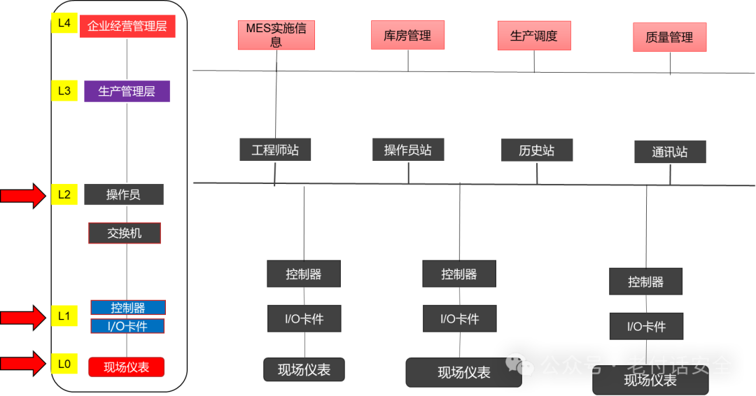
This issue mainly clarifies the interconnection of field devices and explains it clearly. In the next issue, we will focus on clarifying the message structure and functions of industrial protocols. See you next time!┏(^0^)┛