

The most frequently used PLC programming languages currently are Structured Text and Ladder Diagram. For technicians with little foundation, starting to learn PLC programming from Ladder Diagram is the quickest. Regardless of the PLC brand, the structure of Ladder Diagrams is very similar to actual electrical control circuits. Below, we recommend several commonly used control circuits.
1
Start, Hold, and Stop Circuit

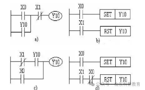
The four Ladder Diagrams to implement the start, hold, and stop for Y10 are shown in the figure. These Ladder Diagrams can all achieve the functions of start, hold, and stop. X0 is the start signal, and X1 is the stop signal. Diagrams a and c use normally open contacts of Y10 to achieve self-locking hold, while diagrams b and d use SET and RST instructions to achieve self-locking hold.
Multi-Location Control Circuit
2
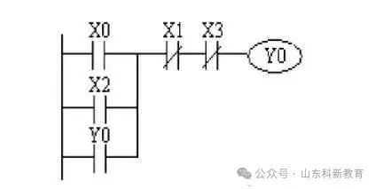
The following diagram shows a program controlling a relay coil from two locations. X0 and X1 are the start and stop control buttons for one location, while X2 and X3 are the start and stop control buttons for another location.
3
Interlocking Control Circuit
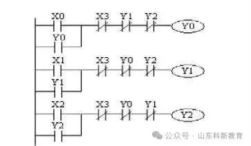
The following diagram shows an interlocking circuit for three output coils. X0, X1, and X2 are the start buttons, and X3 is the stop button. Since Y0, Y1, and Y2 can only be connected one at a time, the normally closed contacts of Y0, Y1, and Y2 are connected in series with the control circuits of the other two coils.
Sequential Start Control Circuit
4
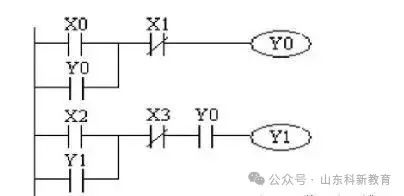
As shown in the figure, the normally open contact of Y0 is connected in series in the control circuit of Y1. The activation of Y1 depends on the activation of Y0. Thus, Y1 can only be activated when Y0 is activated. When Y0 is deactivated, Y1 is also deactivated, and under the condition that Y0 is activated, Y1 can activate and stop itself. X0 and X2 are the start buttons, while X1 and X3 are the stop buttons.
5
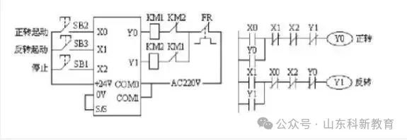
Motor Forward and Reverse Circuit
Centralized and Decentralized Control Circuit
6
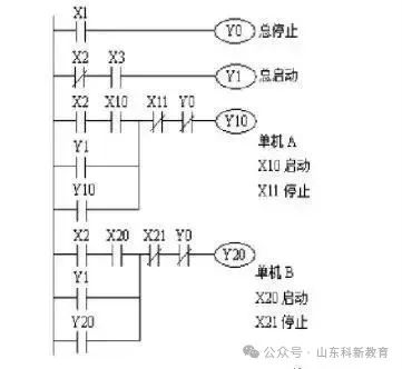
In an automated line composed of multiple machines, there is interlocking between centralized control on the main operation panel and decentralized control on individual machine operation panels. The Ladder Diagram for centralized and decentralized control is shown in the figure. X2 is the selection switch, and its contacts serve as interlocking contacts for centralized and decentralized control. When X2 is ON, it is for decentralized start control; when X2 is OFF, it is for centralized start control. In both cases, both the individual machine and the main operation panel can issue stop commands.
Source: This article is reprinted from the internet, and the copyright belongs to the original author. If there are any copyright issues, please contact us to delete it in a timely manner. Thank you!

Scan to Follow
WeChat ID|13615417996
Follow the QR code on the left to get it for free
[Siemens Data Collection]