STM32 Microcontroller Master-Slave Timer Practical Operation: Precision Control Scheme for Stepper Motors, including Key Complete Code!
Have you encountered issues with inaccurate positioning or stuttering when starting and stopping stepper motors? By using a master-slave timer combination with a microcontroller, these pain points can be easily resolved! Today, I will share a tested and effective control scheme for stepper motors, where the master-slave timers work together to ensure precise starting and stopping of the motor, along with key code that can be directly applied..
1. Core Principle: The “Cooperative Work” of Master-Slave Timers
The core of this scheme is the collaboration between the microcontroller’s Master Timer 1 and Slave Timer 2, which have clear and efficient roles:
• Master Timer 1: Specifically generates PWM pulses, which serve as both the driving signal for the stepper motor and the counting sample for Slave Timer 2.
• Slave Timer 2: Responsible for counting the number of PWM pulses; when the count reaches the preset value, it triggers an overflow interrupt to immediately stop the pulse output of Master Timer 1, achieving precise stopping of the motor.
• Key Advantage: The interrupt mechanism ensures positioning accuracy, with a frequency adjustable range covering 20Hz to 100KHz, suitable for most stepper motor requirements.
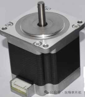
2. Hardware Interface Overview (TB6600 Driver)
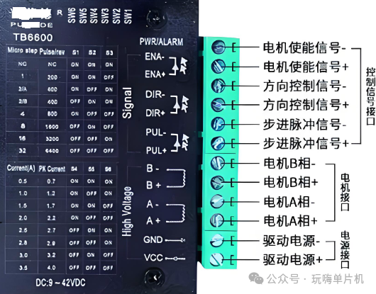
The control core is the signal interfacing between the STM32 microcontroller and the TB6600 driver, with key interfaces as follows:
Enable Signal (ENA): Controls the start and stop of the driver, active high.
Direction Signal (DIR): Switches the motor direction, CW (clockwise) / CCW (counterclockwise) can be configured through code.
Pulse Signal (PUL): Receives the PWM pulses output from Master Timer 1 to drive the motor.
Power Interface: The driver needs to connect to a 9-42VDC power supply, with motor A/B phases connected to the driver motor interface.
3. Core Code Analysis (Directly Portable for STM32)
The code is written for the STM32 microcontroller, with the core divided into three key functions, logically clear and easy to understand:
1. Pulse Output Function (Pulse_output)
Function: Initializes motor direction, pulse frequency, and pulse count, serving as the control entry.
Key Validation: The pulse count must be greater than 0, and the frequency must be within the range of 20Hz to 100KHz; otherwise, it returns an error directly.
Direction Configuration: CW corresponds to motor forward rotation, CCW corresponds to motor reverse rotation, switched via the MODE pin level.
/********************************************
//Stepper Motor Relative Positioning Function
//Cycle: 20Hz~100KHz dir: CW (clockwise direction) CCW (counterclockwise direction)
*********************************************/
void Pulse_output(u32 Cycle,vu32 PulseNum, __IO DIR_Type dir)
{
if(PulseNum<=0) // If the value is less than or equal to 0, return directly
{// Number of revolutions for the stepper motor
printf(“\r\nThe num should be greater than zero!!\r\n”);
return;
}
if(( Cycle<20)||( Cycle>100000))// If the pulse frequency is out of range, return directly
{// Stepper motor running speed
printf(“\r\nThe frequency is out of range! please reset it!!(range:20Hz~100KHz)\r\n”);
return;
}
PWM_Off();// Set the direction signal before establishing the pulse signal
motor_dir=dir;// Stepper motor movement direction
pulsenumber=PulseNum;// Number of revolutions for the stepper motor
if(motor_dir==CW)// Clockwise
MODE_H;// Stepper motor direction configuration
else if(motor_dir==CCW)// Counterclockwise,
MODE_L;// Stepper motor direction configuration
TIM2_config(PulseNum);
TIM_Cmd(TIM2, ENABLE);
TIM_ClearITPendingBit(TIM2,TIM_IT_Update);
TIM_ITConfig(TIM2,TIM_IT_Update,ENABLE);
FRE_TimConfig(Cycle);// The microcontroller generates PWM as the input pulse for the stepper motor
PWM_On();// PWM pulse output
}
2. PWM Frequency Configuration Function and Master Timer Settings (FRE_TimConfig)
The core parameter: stepmotorfre is the motor running frequency, with a value range corresponding to 480~960000 (to meet driver requirements).
Timer Calculation: Dynamically adjust through the TIM_Period parameter to ensure the PWM pulse width is fixed at 50%, ensuring stable motor operation.
Master-Slave Mode Enable: Set Timer 1 as the output trigger source, providing counting signals for Slave Timer 2.
void FRE_TimConfig(u16 stepmotorfre)
{
TIM_TimeBaseInitTypeDef TIM_TimeBaseStructure;
TIM_OCInitTypeDef TIM_OCInitStructure;
RCC_APB2PeriphClockCmd(RCC_APB2Periph_TIM1,ENABLE);
if(stepmotorfre<480) stepmotorfre=480;
// Timer timing time T calculation formula: T=(TIM_Period+1)*(TIM_Prescaler+1)/TIMxCLK=(2400*1/48M)s=0.00005s, which is 20K frequency
TIM_TimeBaseStructure.TIM_Period = 48000000/stepmotorfre-1;
TIM_TimeBaseStructure.TIM_Prescaler =0 ;
TIM_TimeBaseStructure.TIM_ClockDivision = 0; // Clock division
TIM_TimeBaseStructure.TIM_RepetitionCounter = 0;
TIM_TimeBaseStructure.TIM_CounterMode = TIM_CounterMode_Up; TIM_TimeBaseInit(TIM1, &TIM_TimeBaseStructure);
TIM_OCInitStructure.TIM_OCMode = TIM_OCMode_PWM1;
TIM_OCInitStructure.TIM_OutputState = TIM_OutputState_Enable;
TIM_OCInitStructure.TIM_OutputNState = TIM_OutputNState_Enable;
TIM_OCInitStructure.TIM_OCPolarity = TIM_OCPolarity_Low;
TIM_OCInitStructure.TIM_OCNPolarity = TIM_OCNPolarity_High;
TIM_OCInitStructure.TIM_OCIdleState = TIM_OCIdleState_Set;
TIM_OCInitStructure.TIM_OCNIdleState = TIM_OCIdleState_Reset;
TIM_OCInitStructure.TIM_Pulse = (stepmotorfre>>1); // Set the pulse value to be loaded into the capture compare register, taking a fixed 50% pulse width
TIM_OC1Init(TIM1, &TIM_OCInitStructure);
TIM_SelectMasterSlaveMode(TIM1, TIM_MasterSlaveMode_Enable);// Timer 1 as the master in master-slave mode
TIM_SelectOutputTrigger(TIM1, TIM_TRGOSource_Update);// Timer 1 as the output trigger source
TIM_OC1PreloadConfig(TIM1, TIM_OCPreload_Enable);
TIM_ARRPreloadConfig(TIM1, ENABLE);
//TIM_Cmd(TIM1, ENABLE);
// TIM_CtrlPWMOutputs(TIM1, ENABLE);
}
3. Slave Timer Configuration and Interrupt (TIM2_config + TIM2_IRQHandler)
Counting Function: Slave Timer 2 synchronously captures the PWM pulses from Master Timer 1, with a preset counting threshold of PulseNum.
Interrupt Handling: After the count overflow of Slave Timer 2, the interrupt service function immediately closes Timer 1 and 2, stops PWM output, clears the interrupt flag, and completes precise positioning.
/**pulseNum: Controls the number of pulses for the stepper motor operation**/
void TIM2_config(u32 PulseNum)
{
TIM_TimeBaseInitTypeDef TIM_TimeBaseStructure;
NVIC_InitTypeDef NVIC_InitStructure;
RCC_APB1PeriphClockCmd(RCC_APB1Periph_TIM2, ENABLE);
TIM_TimeBaseStructure.TIM_Period = PulseNum-1;
TIM_TimeBaseStructure.TIM_Prescaler =0;
TIM_TimeBaseStructure.TIM_ClockDivision = TIM_CKD_DIV1;
TIM_TimeBaseStructure.TIM_CounterMode = TIM_CounterMode_Up;
TIM_TimeBaseInit(TIM2, &TIM_TimeBaseStructure);
TIM_SelectInputTrigger(TIM2, TIM_TS_ITR0);// Timer 2 Synchronizes counting with the main Timer 1’s PWM
TIM2->SMCR|=0x07; // Timer 2 as a slave timer
TIM_ITConfig(TIM2,TIM_IT_Update,DISABLE);
NVIC_InitStructure.NVIC_IRQChannel = TIM2_IRQn;
NVIC_InitStructure.NVIC_IRQChannelPreemptionPriority = 0;
NVIC_InitStructure.NVIC_IRQChannelSubPriority = 0;
NVIC_InitStructure.NVIC_IRQChannelCmd = ENABLE;
NVIC_Init(&NVIC_InitStructure);
}
void TIM2_IRQHandler(void)
{
if (TIM_GetITStatus(TIM2, TIM_IT_Update) != RESET)
{
TIM_ClearITPendingBit(TIM2, TIM_IT_Update);
TIM_CtrlPWMOutputs(TIM1, DISABLE); // Stop PWM
TIM_Cmd(TIM1, DISABLE); // Disable Timer 1
TIM_Cmd(TIM2, DISABLE); // Disable Timer 2
TIM_ITConfig(TIM2, TIM_IT_Update, DISABLE);
TIM2->CNT =0;
tim2interruptflag=1;
}
}
For friends who enjoy microcontroller programming, have you learned how to precisely control stepper motors using the STM32 microcontroller? Did you master it?
Like and save Follow so you won’t get lost, let’s learn and progress together.