|
This system focuses on communication-related functions for real vehicles, conducting a rapid functionality survey. For IO operations, such as switching sensors, reminders are provided through a “popup + voice prompt” method, achieving semi-automation. |
Before the ECU is installed in the vehicle, we need to find ways to conduct HIL testing, such as basic functional logic testing, diagnostics, flashing, and physical layer protocol testing, to increase the coverage of simulation test cases and avoid functional defects being passed on to the real vehicle.
However, even after HIL simulation testing, we cannot be complacent.
After the vehicle is produced, dedicated engineers still need to conduct a “survey” at the vehicle level to ensure that no basic issues arise.
Survey Items
 The survey mainly includes the following:1. Consistency of Vehicle Message TransmissionFor a project with various configurations of vehicles, automatically analyze the IDs of each network segment to verify whether they are consistent with the parameters defined in the vehicle communication matrix.The traditional testing method involves capturing messages from the vehicle and manually observing the differences from the DBC file, which is extremely inefficient and tedious.A slightly more advanced method is to record messages and replay them using CANoe, utilizing CANoe’s statistical functions, but it still requires manual verification of the discrepancies between CANoe’s statistics and the DBC file, which is also quite laborious.Additionally, Vector has disabled the free message replay function in CANoe version 12.0 and later, meaning that even replaying blf files will now incur costs, requiring a license, which complicates our related work. Moreover, DBC files from most companies are mixed with different configurations and network segments, making testing and verification quite cumbersome.2. Consistency of Vehicle Message Routing and ForwardingIn most cases, there should be at least one gateway in the vehicle, and many messages are forwarded as complete frames, requiring identification of whether the forwarding is normal. For example, the forwarding of the main gateway, domain controller, etc.This work is generally included in the basic functional testing of the gateway and should have been thoroughly tested during the HIL phase. In real vehicle testing, since we cannot actively send messages to the vehicle, we only record messages from each network segment and perform performance analysis on the messages that need to be forwarded.If there are changes in the data area, such as a rolling counter, we can analyze the performance of the forwarding time.The traditional method is also to record blf files and then manually observe them. This repetitive work is a significant waste of human resources and is prone to errors, with low efficiency.3. Terminal Resistance MeasurementTest whether the terminal resistance of each network segment is 60Ω.The traditional method is to disconnect the battery or wait for all vehicle ECUs to enter sleep mode, and then manually measure the terminal electronics of each network segment with a multimeter.4. Testing Message Recovery Capability After CAN Short CircuitFirst, short the CANH and CANL, at which point no messages should be detectable, then disconnect the CANH and CANL, at which point all messages should resume sending.Test the recovery capability for each network segment individually, ensuring that the message sending attributes comply with the vehicle communication matrix definition.5. Testing Continuous Message Sending Capability After Short Circuiting CANH and CANL to GroundSince CAN operates on differential voltage, theoretically, if power isolation is implemented, when CANH and CANL are shorted to ground, the messages should remain unaffected and continue to send.Therefore, when shorting to ground one by one, messages should continue to send, always complying with the vehicle communication matrix definition, especially the cycle.6. Testing Continuous Message Sending Capability After Short Circuiting CANH and CANL to PowerSince CAN operates on differential voltage, theoretically, if power isolation is implemented, when CANH and CANL are shorted to power, the messages should remain unaffected and continue to send.Therefore, when shorting to power one by one, messages should continue to send, always complying with the vehicle communication matrix definition, especially the cycle.7. Reading All Supported Fault Codes from the ECUFor each network segment’s supporting diagnostic ECU, read all the fault codes it can support (which is not the same as stored fault codes) to confirm its “potential”.The traditional method is to disconnect the battery or wait for all vehicle ECUs to enter sleep mode, and then manually measure the terminal electronics of each network segment with a multimeter.At this point, since the diagnostic tool may not have been developed yet, it may be necessary to use CANoe to send relevant diagnostic commands.8. Checking for Non-Cleared Fault CodesFor all network segments and all UDS-supporting ECUs, first execute the action to clear fault codes, then read the fault codes again after a few seconds to determine if there are any non-cleared fault codes.Start the vehicle and check again for any non-cleared fault codes.If there are any, it indicates that the vehicle is not in good health and requires further investigation by relevant professionals.9. AutoSAR Network Management Vehicle Testing (Passive Wake-Up)AutoSAR network management is similar to UDS and belongs to protocol stack functionality, which should have undergone rigorous performance testing during the HIL phase; real vehicle testing only measures basic wake-up and sleep functions.For network segments requiring AutoSAR network management, send virtual wake-up messages, then record and analyze the messages from that segment to see if they comply with the vehicle matrix definition.Stop sending the virtual wake-up messages and check if the segment can achieve sleep within 5-10 seconds; the judgment method for sleep is to send application messages to that segment, which should fail without acknowledgment.10. AutoSAR Network Management Vehicle Testing (Active Wake-Up)Select several local wake-up sources, such as pressing the brake pedal or unlocking the vehicle, then record and analyze the messages from that segment to see if they comply with the vehicle matrix definition.Wait 5-10 seconds to see if the vehicle achieves sleep; the judgment method for sleep is to send application messages to all network segments requiring network management, which should fail without acknowledgment.11. Waveform TestingCAN waveforms are the most important information for analyzing problems, bar none!
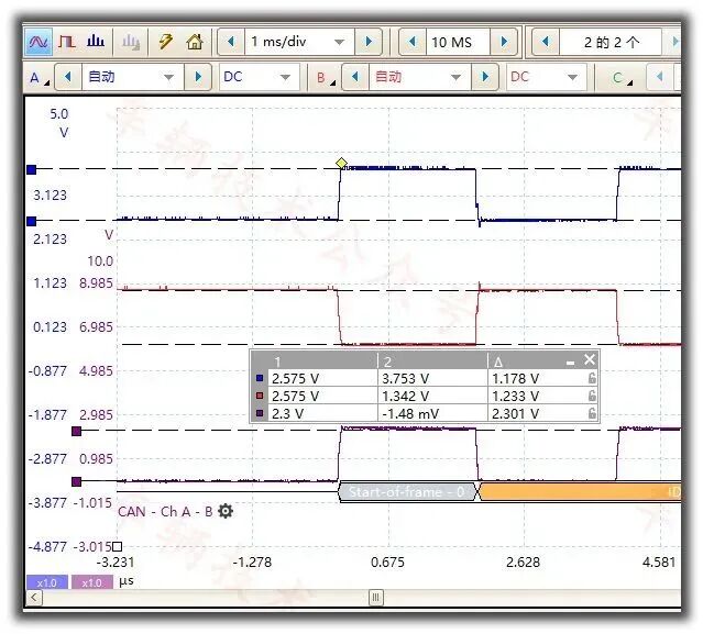
To ensure healthy and reliable communication in real vehicles, we need to record the CAN waveforms of the real vehicle and conduct strict evaluations of the waveforms for each ID to ensure they are accurate, elegant, smooth, and delicate.In the traditional method, engineers carry an oscilloscope, connect a bunch of wiring harnesses, capture the waveforms for each ID, measure bit width, rise and fall times, measure differential voltage, measure spikes, etc.This testing is laborious, extremely inefficient, and a disgrace to our R&D testing peers, especially during repetitive regression testing, where everyone dislikes it and tries to foist it off on newcomers.
Transformative Change
By observing the basic inspection items for real vehicles mentioned above, we can see that the vast majority can be automated.The very few items that cannot be automated, such as pressing the brake pedal or pressing the unlock button, can be addressed through “popup + voice prompts” without affecting the overall level of automated testing.As for the most troublesome waveform measurement, thanks to the intelligent miniaturization of oscilloscopes, PICO, ZLG, and many other manufacturers have released portable oscilloscopes with programmable interfaces, whose sampling rates absolutely meet the testing requirements for CAN and CANFD. They can even record a segment of waveform for a duration, then replay the waveform and perform ID triggering and automated measurement of various waveform parameters, making it incredibly convenient.Our solution is as follows:
| Test Item | Advantages |
| 1. Consistency of Vehicle Message Transmission | Fully automated recording of all network segment messages, automatically analyzing parameters including ID, cycle, DLC, etc.; missed, incorrect, and multiple transmissions can all be automatically detected; among them, incorrect and missed transmissions can directly identify the responsible engineer. |
| 2. Consistency of Vehicle Message Routing and Forwarding | Includes mutual forwarding of CAN and CANFD; in case of missed forwarding, automatically identify whether the source network segment has this message and provide problem cause analysis. |
| 3. Terminal Resistance Measurement | Continuously send application messages to each network segment until successful sending fails (no acknowledgment), then read the resistance value from the resistance meter. |
| 4. Testing Message Recovery Capability After CAN Short Circuit | Individually test all network segments, using programmable relays to control the shorting of CANH and CANL, disconnecting the relay after 5 seconds, recording and analyzing the messages from that segment, and automatically analyzing their consistency with the communication matrix. |
| 5. Testing Continuous Message Sending Capability After Short Circuiting CANH and CANL to Ground |
1) Individually test all network segments 2) Record messages while closing the relay to short CANH to ground for 5 seconds, then disconnect the relay, wait 5 seconds to stop recording, and analyze the recorded messages for consistency with the vehicle communication matrix, especially the cycle. |
| 6. Testing Continuous Message Sending Capability After Short Circuiting CANH and CANL to Power |
1) Individually test all network segments 2) Record messages while closing the relay to short CANH to power for 5 seconds, then disconnect the relay, wait 5 seconds to stop recording, and analyze the recorded messages for consistency with the vehicle communication matrix, especially the cycle. |
| 7. Reading All Supported Fault Codes from the ECU | For the defined networks and ECUs, read each one and automatically compile the supported fault codes into a table for reference and verification. |
| 8. Checking for Non-Cleared Fault Codes |
1) For all network segments and all ECUs, execute the “clear fault, read fault” operation one by one, recording the return values of each ECU into a table, and compiling the fault codes read again into the corresponding table.2) Popup reminder to start the engine. |
| 9. AutoSAR Network Management Vehicle Testing (Passive Wake-Up) | Automatically send messages for all network segments requiring network management and verify whether the messages sent from that segment comply with the communication matrix definition. |
| 10. AutoSAR Network Management Vehicle Testing (Active Wake-Up) | “Popup + voice prompt” to remind engineers to operate local wake-up sources and automatically judge and record subsequent wake-up and sleep conditions. If local wake-up sources are defined for each network, more precise judgment and analysis can be performed; if not defined, at least one network segment must wake up. |
| 11. Waveform Testing | Invoke the oscilloscope to automatically obtain the waveforms of all IDs and measure various waveform parameters one by one to ensure healthy and robust CAN communication. |
Cost-Effectiveness Advantages
Advantage 1: High Automation, Almost Error-Free, Highly Reliable.Except for needing to operate local wake-up sources as prompted and starting the engine when reading faults, almost no manual operations are required. During manual operations, the testing software will be in a waiting state, proceeding only after the operation is completed and confirmed.Thanks to the characteristics of automated testing, it is almost impossible to make errors, which is much better than manual analysis.Regression testing is no longer a painful task; it can be completed in no time.Advantage 2: Low Cost.The entire system is cost-effective, and there is no need to use the Vector toolchain; the total cost of all used hardware does not exceed 100,000 yuan.Advantage 3: Open Source.Developed in LabVIEW, it is simple and intuitive, quick to implement, and easy to learn, helping you and your company quickly build capabilities in this field and improve the quality of mass-produced vehicles.
At the very least, it can help your company cultivate the following capabilities:
| 1 | LabVIEW calls the CAN card to send and receive CAN messages |
| LabVIEW calls programmable relays to control various relays for CAN short circuits, CAN to ground, and power short circuits | |
| LabVIEW implements reading and writing of diagnostic commands, reading fault codes, clearing fault codes, and reading all supported fault codes. | |
| LabVIEW implements big data analysis, such as verifying the consistency of real vehicle messages and communication matrices. | |
| LabVIEW reads and writes third-party files, such as Excel, TXT, or even server interfaces, for reading test cases and generating test reports. | |
| LabVIEW calls oscilloscopes to measure various parameters and obtain specific waveforms. | |
| LabVIEW calls resistance meters to automatically measure terminal resistance. |
Let’s work together to promote the upgrade of automotive R&D testing levels and continuously improve automotive quality.[Recommendation]
Bus Lecture 10: The Best Excel to DBC Tool in the Eastern Hemisphere, Always Free to Give Away