
During the technical exchange meetings of oscilloscopes, we learned that some customers need to understand the rise slope of CAN signals. They usually measure some values and then calculate manually. The ZDS2022 oscilloscope will save you a lot of time by displaying the results directly without manual calculations!
The operation is very simple. First, connect the CAN signal to the oscilloscope to stabilize the trigger and display it on the screen. Then, activate the one-button cursor measurement by turning knob B to accurately position the cursor. Press knob B briefly to switch the cursor line, and press the Cursor button briefly to change the cursor’s display mode.
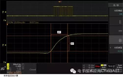
Figure 1: Automatic Slope Calculation Chart
When positioning the cursor, pay attention to the consistency of the X and Y cursor positions. When Y1 is above (or below) Y2, X1 should be to the left (or right) of X2, because the automatic slope calculation is signed. If the order of the cursors is reversed, the sign of the slope may be opposite.
At this point, you will see the measurement result of ΔY/ΔX in the lower left corner of the screen. This feature is very practical! The ZDS2022 oscilloscope helps you easily handle slope measurement, with results displayed automatically, truly meeting your needs!