【Question 1】Do SIS and DCS valves need to be set up separately? Can SIL1 and below be shared?
【Answer】1)Refer to “Design Specifications for Safety Instrumented Systems in the Petrochemical Industry” (GB/T 50770-2013):
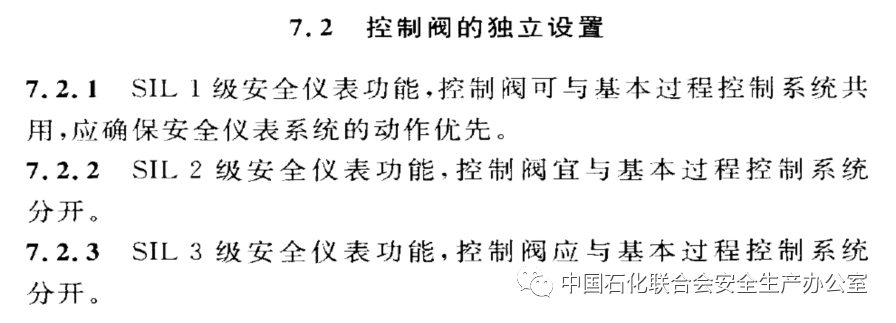
Measurement and actuators are best set up independently. When control valves are shared, it should ensure thatSIS takes priority.
2)Refer to “Acceptance Specifications for Full Process Automation Control Renovation of Key Chemical Enterprises in Jiangsu Province (Trial)” Article 5.1.8, the safety instrumented system should comply with GB50770 requirements, and safety integrity level (SIL) should be level 2 or above, and should be set up independently. For reference!
【Question 2】Do the static grounding clamps for loading and unloading vehicles need to be regularly inspected? How to test their effectiveness?
【Answer】Users can regularly test and keep records, checking whether the alarm goes off when not grounded during on-site inspections.
On-site checks include removing the ground clamp, opening the clamp, and if it does not alarm, it is unqualified; if it alarms, it is qualified. The grounding resistance value should be measured by electrical professionals and should not exceed 10Ω. Note that this is different from grounding electrical equipment; the grounding of loading and unloading vehicles mainly concerns the reliability of the clamp’s grounding and whether the grounding point is effectively conductive. Each grounding should effectively verify the alarm.
Regular checks include:1)Checking for welds at the grounding wire connection that are open or poorly connected; 2)Loose bolts at the connection of the grounding wire to electrical equipment; 3)Mechanical damage, broken strands, or chemical corrosion of the grounding wire; 4)Grounding bodies exposed due to rain erosion or soil removal; 5)The grounding resistance value of the grounding device should not exceed the specified value. For reference!
【Question 3】Can the cabinets of different workshops be set up in one room? How to consider the spacing when placing the cabinets of Class A workshops in Class C workshops?
【Answer】(1) There are no clear requirements in relevant standards or specifications; some smaller factories even design monitoring signals from different workshops in the same cabinet.
(2) The cabinet room stores electronic cabinets, according to the building code “Fire Protection Design Specification for Construction” (GB 50016-2014), the cabinet room should belong to Class E, and cannot classify the cabinets serving Class A, B, and C workshops as Class A, B, and C.
(3) According to the classification of fire hazards in production, there should be fire separation distances that meet the requirements between buildings, and the fire separation distance between the cabinet room and production devices should be determined based on the fire hazard of the production device and the closest distance to the cabinet room. Therefore, the fire separation distance L1 requirement is the same whether the cabinet room of Class A device G is near Class C device A or the cabinet room of Class C device G is near Class C device A. Similarly, the fire separation distance L2 requirement is the same whether the cabinet room of Class A device G is near Class A device B or the cabinet room of Class C device G is near Class A device B. The choice of L1 and L2 depends on the classification of fire hazards of devices A and B, and is not closely related to cabinet room G.
In practice, it is generally not preferred to place cabinets from different workshops together, mainly to avoid human error in opening the wrong cabinet door during maintenance, which is unrelated to fire separation distance. For reference!
【Question 4】Is dichloromethane a major hazard chemical? Is it mainly concentrated on whether it is acutely toxic J4 or J5?
【Answer】Dichloromethane is not acutely toxic J4 or J5. According to the “Catalog of Hazardous Chemicals (2015 Edition)” (Announcement No. 5 [2015] by the State Administration of Work Safety and other ten departments), dichloromethane is classified as a hazardous chemical. Referring to “Identification of Major Hazard Sources of Hazardous Chemicals” GB18218-2018 Table 1, dichloromethane is not included in the hazardous chemicals listed in Table 1. According to the MSDS, dichloromethane belongs to Class 6.1 toxic substances, with acute toxicity LD50: 1600-2000 mg/kg (oral in rats), and according to the “Classification and Labeling of Chemicals Specification” GB3000.18-2013, it falls into category 4 for acute toxicity, and does not meet the requirements of acute toxicity J1-J5 in Table 2 of “Identification of Major Hazard Sources of Hazardous Chemicals” GB18218-2018, and dichloromethane has no storage critical quantity. For reference!
【Question 5】Can DCS, SIS, and GDS share a UPS?
【Answer】 The power supply for the Safety Instrumented System (SIS), Distributed Control System (DCS), and Gas Detection and Alarm System (GDS) is classified as a particularly important load within the first-level load and should be powered by an Uninterruptible Power Supply (UPS). Sharing a UPS for SIS, DCS, and GDS systems meets current standard requirements, complies with safety and reliability mechanisms, and satisfies safety production needs. For reference!
【Question 6】What are the main components of a safety instrumented system?
【Answer】According to “Functional Safety of Safety Instrumented Systems in Process Industry Part 1: Framework, Definitions, System, Hardware and Software Requirements” (GBT 21109.1-2007) Article 3.2.72: The instrument system used to implement one or several instrument safety functions can consist of any combination of sensors, logic solvers, and final elements.
The main components of a safety instrumented system include measuring instruments (referred to as sensors by IEC), controllers (referred to as logic solvers by IEC), and actuators (referred to as final elements by IEC). For reference!
【Question 7】What does the SIL assessment include?
【Answer】Refer to “Design Specifications for Safety Instrumented Systems in the Petrochemical Industry” (GB/T 50770-2013)
Article 4.2.1 states that the safety integrity level assessment should include determining the safety integrity level of each safety instrument function; determining diagnostic maintenance and testing requirements, etc.
4.2.2 The methods for assessing safety integrity levels should be determined based on the complexity of the process, current national standards, risk characteristics, methods for risk reduction, personnel experience, etc. The main methods should include protection layer analysis, risk matrix method, corrected risk graph method, empirical method, and other methods.
4.2.3 The safety integrity level assessment should preferably be conducted in a review meeting. The main documents for review should include process piping and instrumentation diagrams, process specifications, device and equipment layout diagrams, hazardous area division diagrams, safety interlock cause-and-effect tables, and other relevant documents. The main personnel participating in the assessment should include experts from process, process control (instrumentation), safety, equipment, production operations, and management. For reference!
【Question 8】Where does the SIL verification data come from?
【Answer】Reliability data for measuring instruments and control valves used for SIL verification can come from the company’s past actual usage reliability data (preferred), product SIL certification report data, publicly available industrial databases, or manual data. Any of these sources of reliability data comply with current standard requirements. For reference!
【Question 9】Do the measuring instruments and actuators of the safety instrument system need SIL certification?
【Answer】The SIS programmable logic controller should obtain functional safety certification from a nationally authorized certification authority. Measuring instruments, control valves, and actuators do not require mandatory SIL certification. Relevant SIF should meet the requirements of safety integrity levels. For reference!
【Question 10】Which standard should be referred to for the UPS power supply duration requirements of the GDS system?
【Answer】See“Power Supply Design Specifications for Instruments”(HGT 20509-2014)
Article 7.1.3 requires that the power supply time of the AC uninterruptible power supply backup battery should not be less than 30min;
Article 7.2.5 requires that the technical indicators of the DC UPS should meet the backup battery power supply time of not less than 30min.
For reference!
【Question 11】Is it reasonable for the SIS valve to be fail-closed, and after normal gas source pressure, the valve automatically opens?
【Specific Issue】”The SIS cut-off valve for the discharge of the phosphorus trichloride storage tank in the tank area is in fail-closed mode, automatically closing when the gas is cut off and automatically opening when the gas is restored. There is no reasonable explanation or institutional regulation for this automatic recovery,” this is a question raised by experts during the inspection. After a gas source failure, the SIS valve is fail-closed, and after normal gas source pressure, the valve automatically opens. Experts say this design is unreasonable and requires manual confirmation before opening. How do experts view this issue?
【Answer】1. Interlock actions and gas source failures are not the same scenario; interlock actions require manual confirmation for reset operations, while gas source failures generally do not require reset unless there are special requirements in the design process, but that is another matter.
If the safety requirements of the process state that the valve must be confirmed after closing, then redesign the interlock circuit and logic accordingly.
2. Logically achievable things are not difficult.
For interlock conditions, if the valve needs to be opened, it usually requires manual reset. The closure of the valve due to purified compressed air is another factor leading to closure. In both cases, the confirmation needed is what consequences will arise if the valve automatically opens after closure. Based on the consequences, consider what interlocks (interlocks) and operating procedures are needed.
3. Regarding the inspection issue, it is simple; find the design unit to verify and confirm whether there are special requirements. Usually, the response will be that there are no special requirements, then maintain the status quo. If the response indicates that there are special requirements, then conduct a risk analysis for the scenarios with special requirements and provide engineering implementation measures and plans. In practice, it is usually not the case that a gas source failure occurs and then self-recovers; during this period, operators will usually notice, such as various alarms in the DCS. Additionally, adding a function requires consideration of the potential adverse factors it may bring, which needs to be analyzed comprehensively. In simple terms, usually, no special consideration and settings are needed. If there is indeed a significant risk in automatic opening, then conduct a specific analysis accordingly.
Some experts hold the following views:
1. After the gas source is restored, the SIS-controlled valve should only automatically open after confirmation; there is a safety condition confirmation process here; if the gas source is restored and the valve opens directly, abnormalities on-site may not be detected immediately, affecting subsequent processes.
2. Regarding the discussion of SIS valves above, in the LNG industry, there are indeed projects where the SIS valve in the tank area FC requires on-site reset after being triggered for any reason before being reused, which is not an unusual practice. The “Beihai Liquefied Natural Gas Company 11.2 major fire accident” was caused by a cut-off valve that suddenly opened (due to operator error) leading to hydrocarbons entering the maintenance work area, resulting in significant casualties. Experts’ concerns may not be unfounded, as there are too many possibilities on-site.
Based on this question, the following expansions are made:
1. Fail-safe design exists at all levels; SIS has fail-safe design, control valves have fail-safe design, and systems have fail-safe design. Unless otherwise specified, interlock logic control does not monitor the control valve gas source system, and the logic does not include related factors.
Usually, there is no reset confirmation set for gas source failures when the gas source is restored. For example, for the emergency shut-off valve of FC, normally in the “open” state, when the gas source fails, the control valve automatically closes, and when the gas is restored, the control valve’s state depends on the solenoid valve’s state. Expanding the scope, for the control valve of FC, when the gas source fails, the control valve automatically closes, and when the gas is restored, the control valve is in the “control state,” including SIS interlock control or DCS automatic control.
If no other conditions change, the SIS output and DCS output remain unchanged, the control valve will return to the state before the gas source failure. For SIS interlock control, as long as no interlock is triggered during this period, the working condition remains normal, the control valve will generally reopen. For DCS control valves, since the control valve is closed, it is equivalent to a half-open loop, and the PID proportional-integral-derivative will still operate, and the DCS AO output will change, and the control valve will reach a certain opening after the gas source is restored under the drive of the valve positioner.
If the FC control valve, after a gas source failure, is forced to close, and upon restoration of the gas source, the control valve automatically opens or opens to a certain position, there will be adverse effects and risks, then a risk analysis should be conducted, and safety protection measures and plans should be determined.
In general, there will be no risk. For example, for interlocks, the FC cut-off valve, normally open, when the gas source fails, is forced to close, and when the gas source is restored, if the process state is normal, then the cut-off valve will open without danger. If the process state has changed, if interlock conditions are triggered, the SIS interlock will naturally act, and the SIS output will naturally reverse state, and at this time, the FC cut-off valve will not automatically open when the gas source is restored.
For control valves, normally, the control valve is in a control state, in automatic adjustment, when the gas source fails, it is forced to close, and the loop is in a half-open state, operators will quickly notice, and it is highly likely that they will switch the loop to manual mode and have someone check on-site.
Standard situation:
According to the “Signal Alarm and Safety Interlock System Design Specification” (HG/T 20511-2014) Article 4.1.5, the safety interlock system should be designed to maintain a safe state until a manual reset is performed.
The article states that 4.1.5 reset is generally achieved by manual operator action and does not use automatic reset, as automatic reset during the startup process may pose potential dangers. When the safety interlock system performs multiple actions, the interlock reset should ensure that each final element remains in a safe state, and then step-by-step start the final elements according to the process operation manual.
Note: The text of 4.1.5 states that the safety interlock system should be designed to maintain a safe state until a manual reset is performed. It does not include the situation of gas source failure of on-site control valves, only includes the scenario of the safety interlock system maintaining a safe state.
If the FC control valve, after a gas source failure, is forced to close, and upon restoration of the gas source, the control valve automatically opens or opens to a certain position, there will be adverse effects and risks, then a risk analysis should be conducted, and safety protection measures and plans should be determined.
2. Sometimes monitoring certain situations on-site is beneficial; for example, in some cases, it is necessary to set up a control valve air storage tank, and in certain situations, setting pressure monitoring for the control valve gas source system and remote alarms is very good; otherwise, it is difficult to detect gas source failures.
According to the “Automation Instrument Selection Design Regulations” (HG/T 20507-2014) Article 11.9.9, the setting of air storage tanks should meet the following requirements:
1. When the interlock position of the valve and the gas source failure position are inconsistent, an air storage tank should be set up to ensure that the valve is in the required position during interlock.
2. According to the requirements of process control, air source facilities with storage tanks should be equipped.
3. Double-acting cylinders (which cannot achieve spring return) require that the valve be in a safe position during gas source failure and should be equipped with an air storage device.
According to the “Signal Alarm and Safety Interlock System Design Specification” (HG/T 20511-2014) Article 4.1.5, the safety interlock system should be designed to maintain a safe state until a manual reset is performed.
The article states that 4.1.5 reset is generally achieved by manual operator action and does not use automatic reset, as automatic reset during the startup process may pose potential dangers. When the safety interlock system performs multiple actions, the interlock reset should ensure that each final element remains in a safe state, and then step-by-step start the final elements according to the process operation manual.
3. The selection of FC, FO, FLC, FLO, and FL for control valves is determined based on the process.
In general, the FC, FO, FLC, FLO, and FL of control valves are consistent with the interlock direction, which is a relatively determined safe position.
In special cases, the FC, FO, FLC, FLO, and FL of control valves may not be consistent with the interlock direction, indicating that there is no absolute safe position, only a relatively safe position.
What does F represent in FC, FO, FLC, FLO, FL of control valves? Different books, different specifications, different process packages, and patents may have different requirements; some F represents gas source failure, while others represent gas source failure and power failure, etc.
PIP standards and SHELL standards indicate that in certain scenarios, SIF reset equals three procedures:
① The condition that triggered SIL disappears, permission;
② The position of the key control valve (if any) is compared with the control loop output value and the safe position for permission;
③ Control room reset or on-site reset;
However,② is often found missing or incorrectly implemented in current designs.
But the general situation in engineering does not represent that all scenarios are like this; specific issues need to be analyzed specifically. The above standards are listed to illustrate these situations.
For example, automatic reset is generally not recommended, but in certain special circumstances, automatic reset may be required. Also, conditions for reset, etc.
Additionally, some details, such as some projects using air storage tanks, double solenoid valves, etc., but the related configurations are not in place. Some have even done it incorrectly, such as in some cases where double solenoid valves are designed as 2-out-of-1 configurations instead of 2-out-of-2. Of course, these need to be analyzed specifically.
Based on this, the diagram should clearly depict the details of the switch valve configuration and type codes, and the PID should clearly specify the configuration of that type.
For reference!

Disclaimer: The above content is organized from the daily discussion and exchange content of the “HSE Think Tank Group” of the Petrochemical Federation and does not represent the views of any regulatory authority, for reference only for industry professionals!
My skills are limited, and if there are any inaccuracies, please feel free to leave comments for criticism and correction, so we can improve the Q&A collection.
We also welcome everyone to leave HSE-related questions for discussion.
Organized by: Chen Xinli、Jin Long、Ma Mingxing、Zhou Yuting、Luo Dongming、Zhou Qinging、Wang Dongmei、Kong Xiangyun、Ma Shangjie、Huang Chunyan、He Jiangfeng、Hou Weiguo、等
Reviewed by: Shi Hongxi, Zhu Chuanwei, Yang Wenhai, Yu Juan, Zhang Wu, Cui Yuanhai, Shen Qingyang, Qiu Jingmin, Ji Taotao, Hu Pingjie, Lin Zhenyuan
Thanks to: Experts from Hu’an.
Special thanks to: Ye Xiangdong, Pei Bing’an, Li Yuming, Fan Yongfeng, Lin Hongjun, Liu Zhibao, Zhang Sipei, Zhang Zuoben, Qiu Jingmin, He Long, Liu Tao, Zhen Hongyun, Yang Honglei, Yan Changling, Sun Shu, and other experts.
For more exciting content, click the blue text above to follow us.