During the missile development process, to assess its anti-jamming performance, an infrared jamming source deployment device needs to be installed on the target aircraft. Within a specific time frame after the target aircraft takes off, infrared jamming munitions are deployed according to a certain sequence, creating an infrared radiation source around the target aircraft that resembles its infrared radiation characteristics, thereby interfering with the missile.
Previously used deployment devices had a fixed deployment mode: either all deployed at once or deployed at fixed time intervals. Moreover, the settings for the deployment mode were solidified within the device before the target aircraft took off and could not be modified again. This relatively fixed deployment mode could not fully validate the missile’s anti-jamming performance indicators. Additionally, if errors were found in the deployment mode settings after the target aircraft took off or if a temporary change was needed, it could not be reloaded, wasting testing opportunities. These factors severely restricted the effective conduct of missile target range tests.
The airborne remote deployment control terminal, with DSP as the control core, utilizes a wireless data transmission radio to receive control instructions from the ground station, demodulating the received wireless communication data for reception and storage. It sets the deployment mode and responds to ignition commands, using the processor’s digital I/O signals to complete the ignition control of the infrared jamming source, thereby accomplishing the deployment tasks of the target aircraft.
1 Hardware Circuit Design
1.1 System Composition Structure
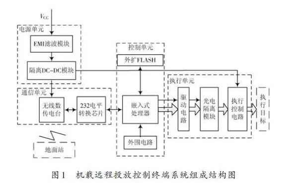
The airborne remote deployment control terminal adopts a modular design, mainly composed of four parts: communication unit, power supply unit, control unit, and execution unit. The communication unit uses a wireless data transmission radio for remote communication with the ground station; the power supply unit isolates and converts the DC power supply on the target aircraft to match the power consumption of the deployment control terminal; the control unit receives instructions from the ground station, configures the deployment mode, controls the execution unit based on the instructions, and feeds back the terminal’s status to the ground station through the communication unit; the execution unit receives instructions from the control unit and controls the deployment of each infrared jamming munition on the target aircraft separately.
Figure 1 shows the system composition structure diagram of the airborne remote deployment control terminal.
1.2 Communication Unit Design
Figure 2 shows the communication unit schematic diagram.
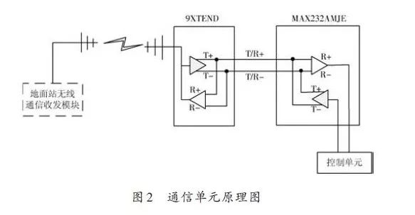
The communication unit mainly consists of a wireless data transmission radio and a level conversion chip, completing the wireless data communication function. The wireless data transmission radio uses the MaxStream 9Xtend-PKG-R frequency-hopping data transmission radio module. The main features of this module are that it can transmit over longer distances using spread-spectrum communication methods under the same transmission power. Additionally, using the FHSS frequency-hopping spread-spectrum method and AES data encryption feature of this module can avoid RF interference from other wireless systems.
Both the airborne remote deployment control terminal and the ground station use the same model of wireless data transmission radio, allowing the communication data between the control terminal and the ground station to be directly retrieved from the data port without special settings. The wireless data transmission radio uses an integrated RS 232 bus interface for data transmission with the DSP processor, utilizing the MAX232AMJE chip to complete the data send/receive level conversion.
1.3 Control Unit Design
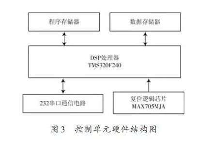
The hardware structure of the control unit is shown in Figure 3. The processor uses TI’s TMS320F240, which provides a 10-bit resolution A/D, a 16-bit precision timer function, a 16-bit precision watchdog timer, a full-duplex serial interface, and an integrated 32 KB FLASH program memory. In the control unit design, 64 KB of external program memory and 64 KB of data memory are expanded. The TMS320F240 has the hardware conditions for developing the IPA system; it only requires the RS 232 serial communication port, placing the loading code in the FLASH custom segment, utilizing this code to erase FLASH and read the code from the program memory.
The reset logic circuit mainly improves the system’s reliability, using a dedicated reset logic chip MAX705MJA to achieve reliable system reset. In addition to power-on reset and power-down reset, the MAX705MJA also monitors the system’s power supply and provides data protection. When the monitored power supply voltage is abnormal, it provides an interrupt request signal, facilitating the system’s abnormal handling; simultaneously, when the system program runs away or deadlocks, the watchdog timer will automatically reset the system, returning it to normal working status and allowing the program to resume normal operation.
1.4 Execution Unit Design
Figure 4 shows the hardware schematic diagram of the execution unit.
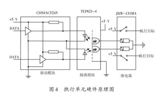
After receiving the ignition command, the processor of the airborne remote deployment control terminal issues control signals through digital I/O, passing through the CD54ACT245 driver module, using TLP621-4 for optical isolation of the control signals, and controlling the relay JRW-131MA to send the ignition power signal to the target, achieving the execution of the target. Since each execution target is controlled by a separate relay, it is convenient to realize the diversity of the deployment mode.
After receiving the command, the airborne remote deployment control terminal uses the internal 16-bit timer of the DSP for counting, achieving control accuracy at the millisecond level, generating relay I/O control signals according to the required time intervals. At the same time, it uses the A/D module of the DSP to monitor the voltage.
The monitoring results are transmitted to the ground station via wireless communication.
2 Software Design
The software of the airborne remote deployment control terminal mainly completes functions such as system self-check, storage and setting of deployment mode data, execution of deployment commands, collection of ignition voltage and operating voltage, and feedback of terminal working status.
Figure 5 shows the flowchart of the airborne remote deployment control terminal software.
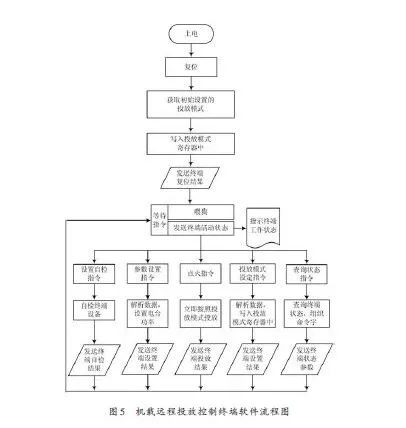
After the system is powered on or reset (software or hardware), the software automatically reads the initial settings on the terminal, writes them into the deployment mode register, and then enters the waiting for instructions state. During the waiting for instructions process, it also sends interrupt activity status. Upon receiving a valid instruction, it enters the instruction execution subroutine, executing it and returning to the ground station. The system subroutines are as follows:
(1) Upon receiving the self-check command, self-check the terminal and send the self-check result command to the ground station.
(2) Upon receiving parameter setting commands, parse the radio transmission power, and after successfully setting the radio transmission power, send a success command back to the ground station.
(3) Upon receiving the ignition command, deploy according to the deployment mode, and after completion, return the deployment completion command to the ground station.
(4) Upon receiving deployment mode settings, parse the deployment mode data, rewrite the deployment mode data register, and after successful modification, send a success command back to the ground station.
(5) Upon receiving the status query command, detect the terminal status and send the data back to the ground station.
The communication code of the airborne remote deployment control terminal adopts a specific data frame encoding principle to minimize the error rate during data transmission while ensuring transmission efficiency. The data frame structure in the system’s transmission protocol uses specific start and end codes for the first two bytes (header) and the last byte (footer), such as AAH, 55H, B5H, etc., which can effectively suppress errors. The receiving side can place the received data in a FIFO buffer, starting to receive a data frame only when a valid header is received; otherwise, it is considered interference or error and discarded. Once the data frame reception starts, it can correctly receive the data code according to the data length, otherwise, it discards and starts waiting for the start code again. Data transmission often has continuous zero bytes, which are very susceptible to interference and can turn into other data; therefore, the data frame adopts a remainder-3 encoding method. Each byte of the data frame uses parity checking and calculates the cumulative sum and XOR sum of all data bytes, placing them in the data frame for the receiving side to verify.
3 Conclusion
The designed airborne remote deployment control terminal, utilizing the resources of DSP, conveniently implements the application of line programming technology, allowing for easy remote loading of deployment modes; the separate control of the infrared jamming source control path makes the setting of deployment modes more diverse; and the combination of software and hardware provides reliability for system operation. This system is user-friendly, reliable, and has been effectively applied in multiple outdoor target tests with good results.