The M580 is Schneider’s medium to large PLC, powerful in functionality, while the S7 200 SMART is Siemens’ small PLC, widely used in industrial settings where communication between two PLCs is often required. The M580 supports both MODBUS TCP and Ethernet/IP industrial Ethernet protocols, and the S7 200 SMART can also function as a MODBUS TCP server through function blocks, allowing for MODBUS TCP communication between them. This example demonstrates how the M580 acts as a client to read and write from the S7 200 SMART.
-
BMEP584040 SV 3.1 Control Expert 14.0 (Unity Pro 14.0);
-
CPU SR20 SV 2.4 STEP 7-MicroWIN SMART V02.04;
-
A laptop with the software installed, and several network cables;
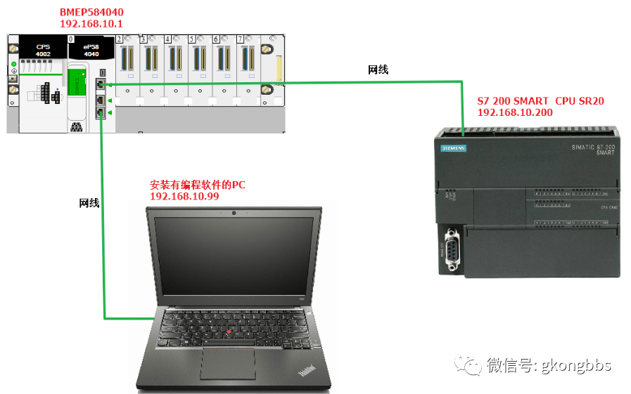
The experiment uses the CPU of BMEP584040, which has three network ports. The first port is the server port, used to connect to the S7 200 SMART, while the second and third ports are device ports, mainly used for connecting Ethernet remote I/O or for connecting a PC for programming. The three ports are internally connected, providing functionality similar to a switch, allowing the PC to also connect to the S7 200 SMART through programming software, as shown in the diagram.
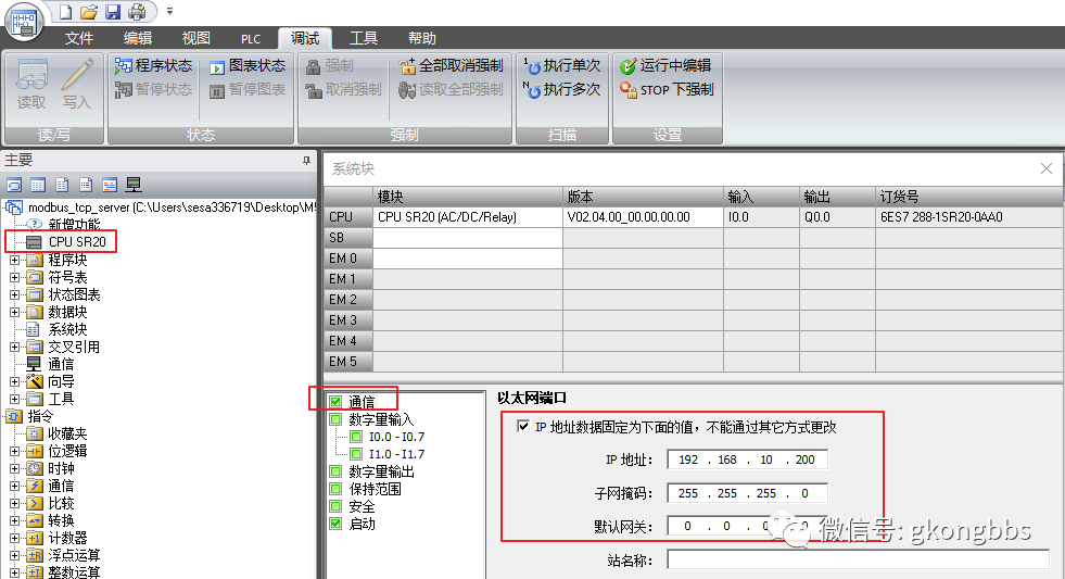
3.1 Allocate an IP address for the S7 200 SMART in the software, as shown in the following image.
3.2Starting from version V2.4, STEP7-Micro/WIN SMART directly integrates the Modbus TCP library instructions into the software, without the need for separate installation or purchase. After installation, the Modbus TCP instructions can be found in the “Library” folder under the “Instructions” folder in the STEP7-Micro/WIN SMART project tree, as shown in the image below. The instructions are divided into client and server types, and the current version of the instructions is V1.0. The client instructions occupy the open user communication resources for active connections, up to a maximum of 8; the server instructions occupy the passive connection resources of the open user communication resources, also up to 8. In this example, the S7 200 SMART acts as a server, so only the MBUS_SERVER function block is called.

3.3 The MBUS_SERVER function block pin description is as follows:
|
Parameter and Type |
Data Type |
Description |
|
|
Connect |
IN |
BOOL |
=1: The server accepts requests from clients; =0: The server can disconnect an established connection |
|
IP_Port |
IN |
WORD |
The local port number of the server |
|
MaxIQ |
IN |
WORD |
Corresponding digital input/output points (corresponding to Modbus address parameters 0xxxx or 1xxxx) Settable range: 0-256, =0 indicates disabling all reads and writes for inputs and outputs. It is recommended to set the MaxIQ value to 256. |
|
MaxAI |
IN |
WORD |
Corresponding analog input parameters (corresponding to Modbus address parameters 3xxxx) Settable range: 0-56. =0 indicates disabling reads for analog inputs. To allow access to all CPU analog inputs, the recommended values for MaxAI are as follows: For CPU CR40 and CR60, set to 0 For all other CPU models, set to 56 |
|
MaxHold |
IN |
WORD |
Number of word holding registers in V memory for Modbus address 4xxxx or 4yyyyy. |
|
HoldStart |
IN |
Dword |
Pointer to the starting position of the holding register in V memory |
|
Done |
OUT |
BOOL |
TRUE: When any of the following conditions are true: the client has connected to the server; the client has disconnected from the server; the client has received a Modbus response; an error has occurred FALSE: The client is busy establishing a connection or waiting for a Modbus response from the server. |
|
Error |
OUT |
BOOL |
Error occurred, valid for only one cycle |
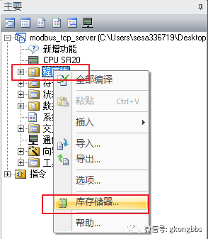
3.4 Set up memory allocation
Right-click on the “Program Blocks” folder and select “Memory” from the menu:
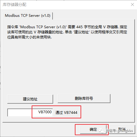
In the memory allocation dialog, manually enter the starting address of the memory area. In this instance, it starts from VB7000 to ensure the instruction library works correctly. Ensure the memory area does not conflict with other addresses already used in the program. Using suggested addresses does not guarantee that there will be no address overlap, so it is recommended to manually input the correct starting address for the memory area. As shown in the image below:
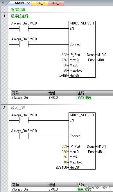
3.5 Write a simple logic program as follows:
The S7 200 SMART as a server can support 8 clients, but each client requires a MBUS_SERVER. In this example, to connect 2 clients, 2 MBUS_SERVER function blocks are called, and note that the IP_Port must be different; one is 502, and the other is 503. Two MBUS_SERVER cannot use the same port.
Port 502 starts from VB0, meaning VW0 corresponds to MODBUS 40001 (VW0 corresponds to VB0 and VB1; VW2 corresponds to MODBUS 40002 (VW2 corresponds to VB2 and VB3))
Port 503 starts from VB100, meaning VW100 corresponds to MODBUS 40001; VW102 corresponds to MODBUS 40002:
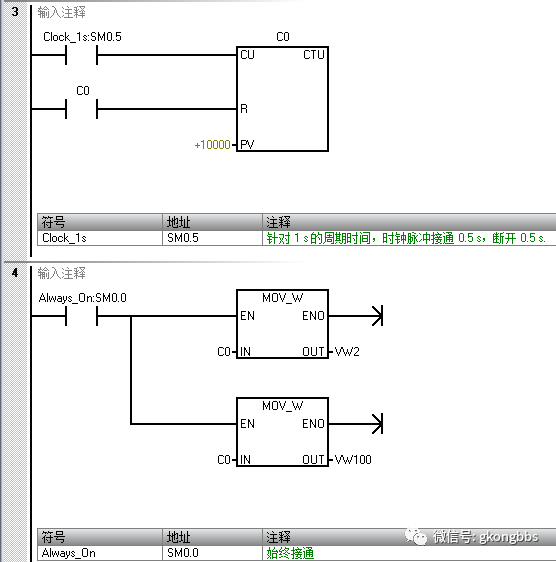
C0 is a counter, CU pin is a 1-second pulse, performing a simple self-incrementing count, then the count value of C0 is assigned to VW2 and VW100. During communication, observe whether the value read by the client changes to determine if the communication is normal.
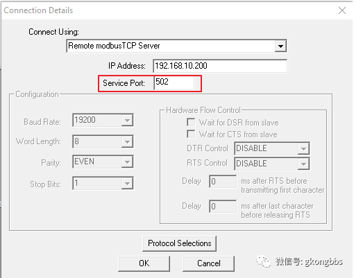
3.6 Download the program to the CPU, start the CPU, and use MODSCAN to test the MODBUS TCP server data of the S7 200 SMART. (MODSCAN is a computer testing tool that can simulate a MODBUS master station)
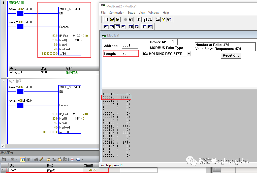
Test the data on port 502, where the number of registers opened by port 502 is 20, testing data VW2 corresponding to 40002:
Test the data on port 503, where the number of registers opened by port 503 is 40, testing data VW100 corresponding to 40001:

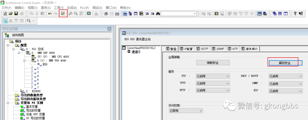
4.1 Open Control Expert (Unity Pro) software, create a new project, select the BMEP584040 CPU, and after creating it, unlock the security as shown in the image below. Unlocking security enables the functions within the CPU service and disables access control. If access control is enabled and not set correctly, it may lead to the software being unable to connect to the CPU via Ethernet after the first program download.

After unlocking, it is necessary to check “Confirm” as shown in the image below. Whenever hardware and configuration are modified in Control Expert, “Confirm” must be checked.
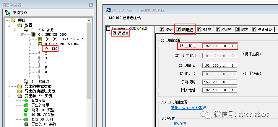
Set the main IP address of the M580 to 192.168.10.1, where IP address A is used to connect to remote Ethernet I/O, which is not used in this example.
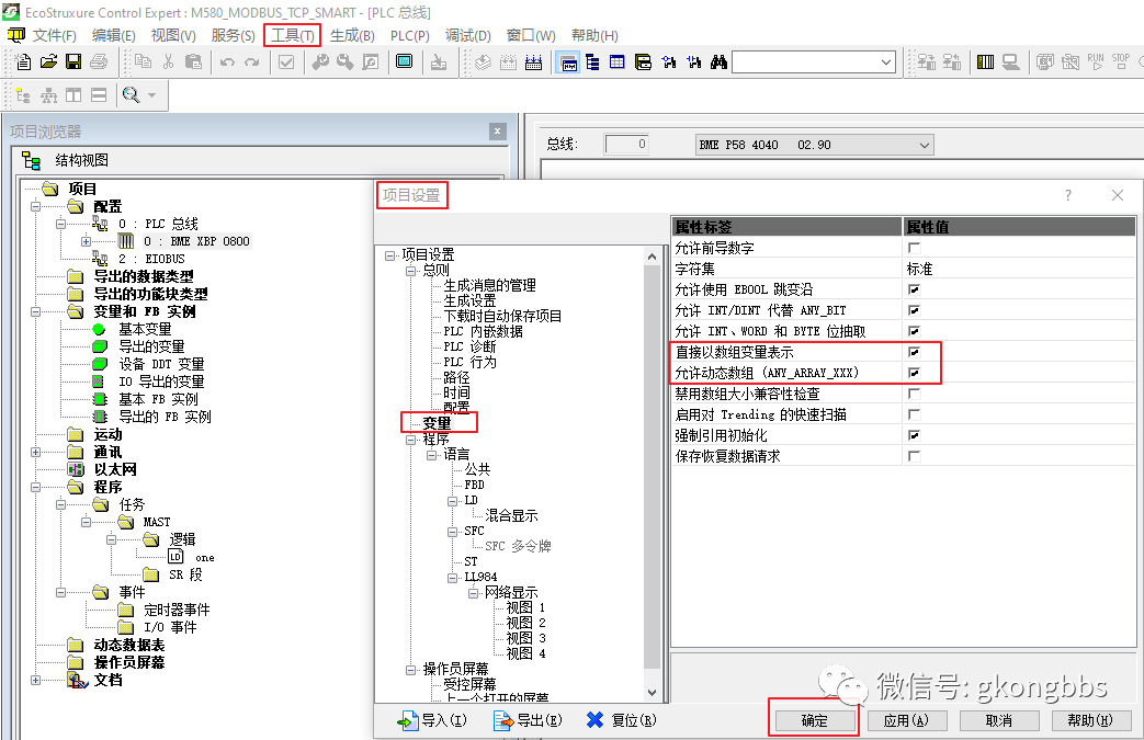
In the “Tools” menu under “Project Settings”, check “Directly Represented by Array Variables” and “Allow Dynamic Arrays”, as shown in the image below. This is to avoid the “Dynamic Arrays Disabled” error when using the READ_VAR and WRITE_VAR function blocks.
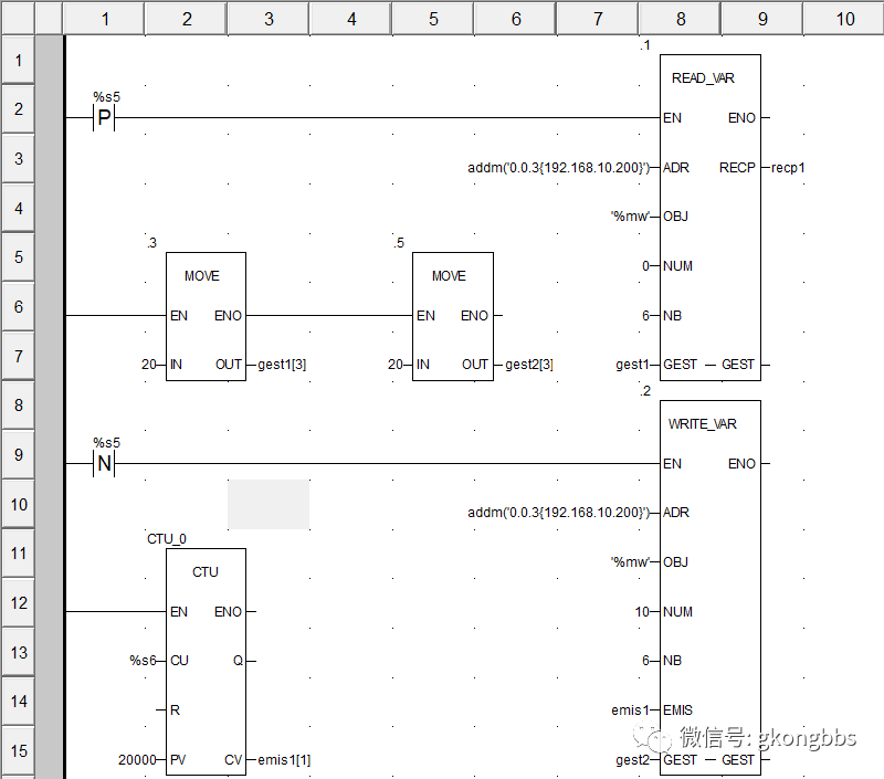
4.2 M580 uses READ_VAR and WRITE_VAR programming to implement MODBUS TCP communication
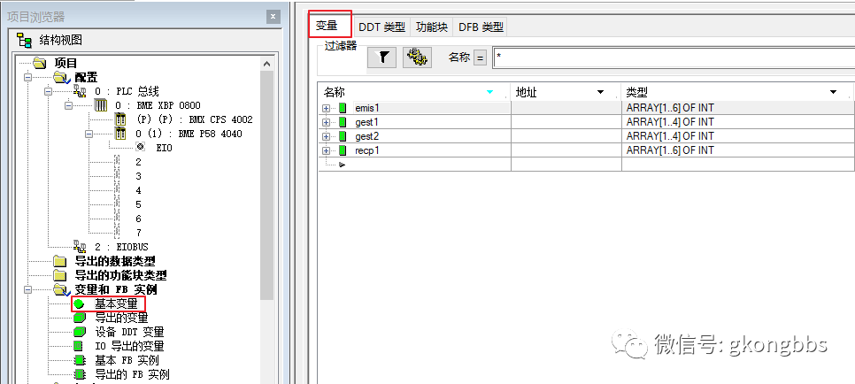
First, create the following variables in the variable table:
In Control Expert software, the MODBUS TCP client function defaults to accessing the server’s port 502, and can only access port 502; other ports are inaccessible.
%S5 is a 100 millisecond pulse, P is the rising edge, N is the falling edge. Since the S7 200 SMART’s port 502 can only accept one request at a time, READ_VAR and WRITE_VAR need to be triggered separately.
Addm is the addressing function block, where 0.0.3 indicates the M580 CPU’s network port (this is the default), and 192.168.10.200 is the IP address of the S7 200 SMART.
OBJ fills the %MW table for reading and writing area 4, NUM is 0 indicating that the starting address for reading is 40001, NB 6 indicates reading 6 words.
GEST is the communication management table, which is an array of 4 integers, where the 3rd integer is the timeout, with a default time base of 100ms. In this example, it is assigned a value of 20, indicating 2 seconds, meaning that after a 2-second communication interruption, it will attempt to reconnect. In Ethernet communication, this timeout must be assigned, and the duration is recommended to be longer than the trigger time of READ_VAR.
RECP is the array where the read data is stored. In this example, 6 words are read, and all recp1 is an array of 6 integers.
WRITE_VAR and READ_VAR pins are generally similar, where EMIS is the array that M580 prepares to write to the other party. Since it needs to write 6 words to the other party, emis1 is also an array of 6 integers.
WRITE_VAR’s NUM is 10, indicating writing to the other party’s 40011, corresponding to the starting address of VW20 on the S7 200 SMART.
Using CTU for a 1-second count, the result is stored in the first element of emis1. During communication, check whether this changing value has been written to the S7 200 SMART to determine if the communication is normal. The program is written as follows:
After completing the program, regenerate all projects. After confirming no errors, download the program to the CPU. For the first download to M580, it is recommended to use a mini USB programming cable. If unavailable, a network cable can also be used.
Simultaneously monitor the programs of M580 and S7 200 SMART online. It can be observed that M580 reads the value of VW2 from SMART and stores it in recp1[2], while M580 writes the value of emis1[1] to SMART’s VW20.

4.3 M580 uses the DTM browser to configure scanning and communicate with S7 200 SMART (For the same S7 200 SMART, using READ_VAR cannot configure scanning, and similarly, if scanning is configured, READ_VAR communication cannot be used)
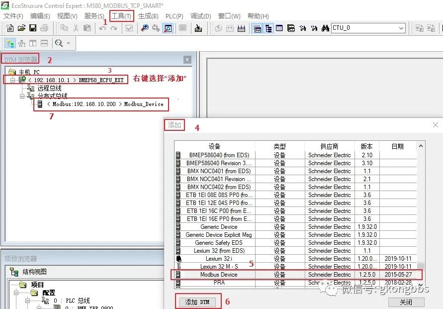
In the “Tools” menu under “DTM Browser”, right-click on BMEP58_ECPU_EXT, select “Add”, and in the pop-up dialog, choose Modbus Device. After adding, a Modbus_Device device will appear under the distributed bus, as shown in the image below:
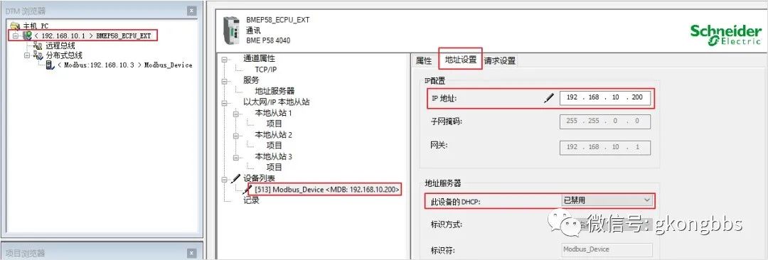
After adding Modbus_Device, double-click on BMEP58_ECPU_EXT, select Modbus_Device under the “Device List”, and set the IP to the S7 200 SMART’s IP address 192.168.10.200. Since the S7 200 SMART’s IP is configured in its software, this “Address Server’s DHCP” needs to be set to “Disabled” (default is Disabled). After setting, click the “Apply” button at the bottom right of the page.
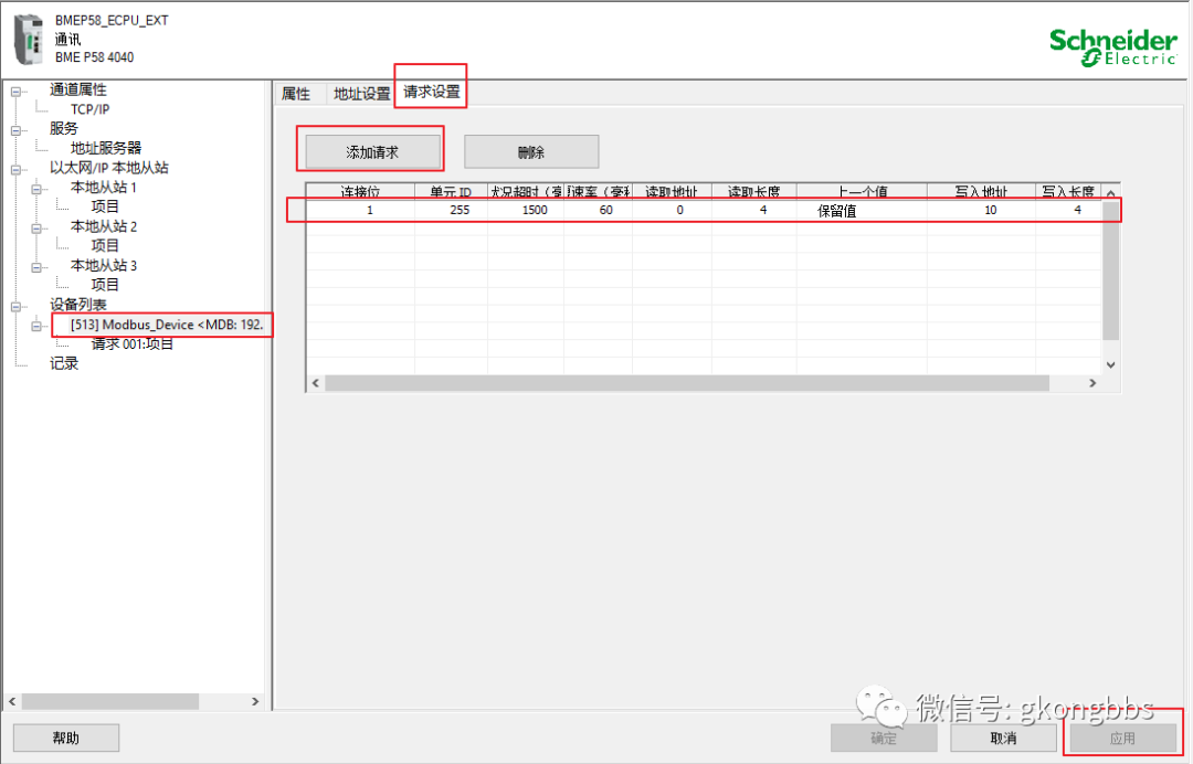
Then select “Request Settings”, click “Add Request”, and a request configuration will appear in the table with connection bit 1, which is automatically assigned.
Unit ID 255 can be used for direct Ethernet devices, while for Modbus TCP to RS485 gateways, this unit ID is the address of the RS485 slave for addressing each RS485 slave under the gateway.
Timeout is set to 1500ms by default. If communication is not successful after 1500ms, an error will be reported.
Repeat rate is 60ms, which is the cycle for this scanning, meaning it scans once every 60ms, and can be modified according to actual conditions.
Read address 0 indicates reading from station 40001;
Read length 4 indicates reading 4 words.
Previous value indicates whether to retain the last communication value when communication is interrupted or set to 0.
Write address 10 indicates writing to station 40011;
Write length 4 indicates writing 4 words.
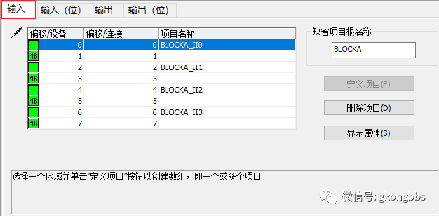
After configuring the request parameters, select “Request 001: Project”, in the input, hold the Shift key on your computer, select 0-7 in blue as shown in the image below, and then click the “Define Project” on the right. In the pop-up “Project Name Definition”, select the data type as INT (this can be defined based on actual conditions), and the project name can also be modified. In this example, the default is selected, and click OK.
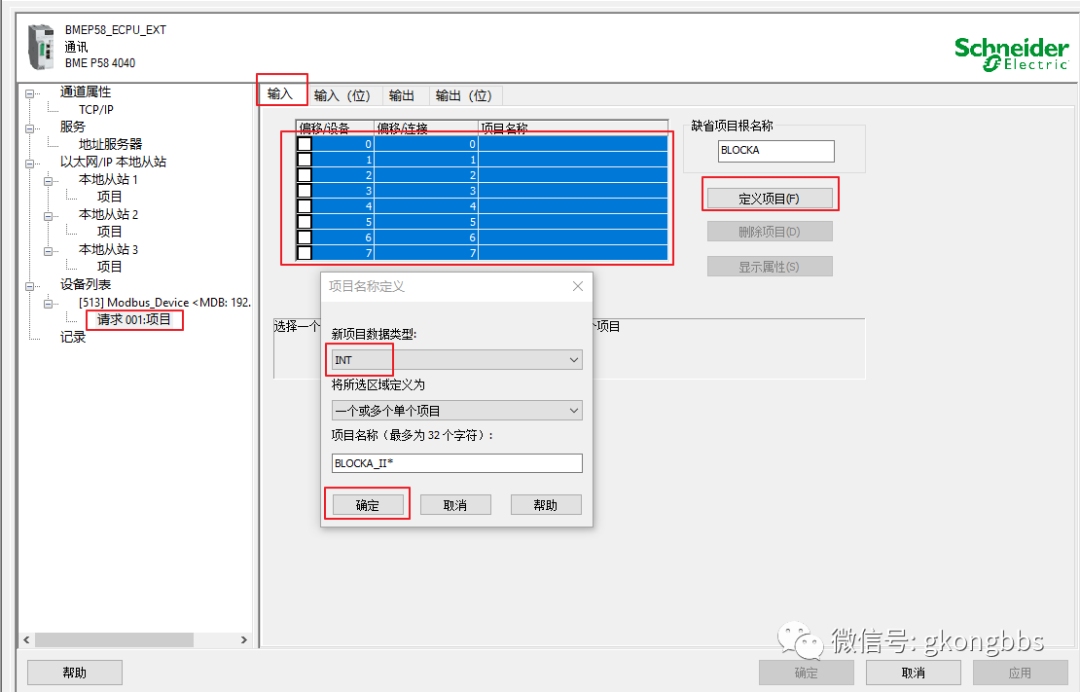
After clicking “OK”, you can see the green box, where 16 indicates 16 bits of data.
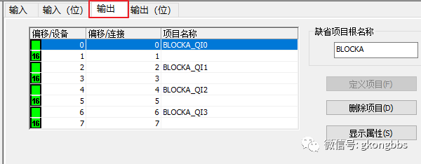
Using the same method, define the output project as shown in the image below:
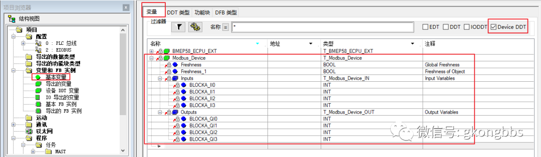
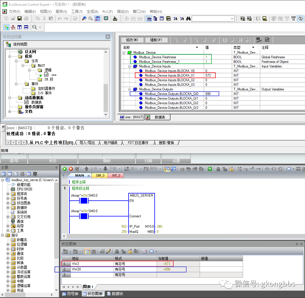
After configuration, click the “Apply” button at the bottom right, confirm, and then regenerate all projects, ensuring that the program has no errors. Double-click on “Basic Variables”, and in Device DDT, you can see the generated Modbus_Device variable, where Freshness and Freshness_1 are communication status variables. If they are 1, communication is normal; if 0, communication is erroneous. Inputs are the data read from S7 200 SMART, Outputs are the data written by M580 to S7 200 SMART.
In the program, add a simple line to MOVE the CTU counting result to Modbus_Device.Outputs.BLOCKA_QI0. This value is written to S7 200 SMART during communication for easy observation of the communication status.
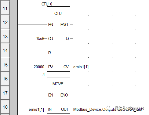
After regenerating all projects and confirming no errors, download the program to the M580 CPU, start M580, and monitor the dynamic data table online. You can see that Modbus_Device.Freshness and Modbus_Device.Freshness_1 both have a value of 1, indicating normal communication, while Modbus_Device.Inputs.BLOCKA_II1 is the value of VW2 read from S7 200 SMART, and M580 has written the value of Modbus_Device.Outputs.BLOCKA_QI0 to VW20 of S7 200 SMART.
5.1 When the S7 200 SMART acts as a MODBUS TCP server, it can support multiple clients accessing it, provided that multiple MBUS_SERVER function blocks are called, and the IP_Port must be different.
5.2 The MODBUS TCP client of Schneider PLC on the Control Expert software platform can only read data from the server’s port 502, and data from other ports cannot be read. This means that if two Schneider PLCs under the Control Expert platform try to read and write to the same S7 200 SMART simultaneously, communication will not succeed.
Similarly, do not use MODSCAN and M580 PLC simultaneously to access the S7 200 SMART server’s port 502. In this example, M580 can access port 502 while MODSCAN accesses port 503.
5.3 The common methods for M580’s MODBUS TCP client communication are two:
One is using the programmed READ_VAR and WRITE_VAR, which supports more MODBUS function codes (if it is function codes 05 and 06, DATA_EXCH must be used), and the communication timing can be controlled by the user, but requires programming skills;
The other is configuring scanning in DTM, which has the advantage of not requiring program writing; as long as configured correctly, it works. However, it is limited to reading and writing MODBUS holding registers (4X registers), and the communication timing is not easy to control.
Disclaimer: This article is reproduced from the Industrial Control Forum, with copyright belonging to the original author. If there are any copyright issues, please contact us in a timely manner for deletion. Thank you!
Full Question Bank for Electrician Primary Exam 2022 (Including Answers)
3 Essential Tools for Electricians, Easily Accessible via WeChat!
[Collection] The “Path” of a Decade-Old Electrician, Secrets to Earning Over 10,000 a Month!
Which of the Five Major Electrical Drawing Software (CAD, Eplan, CADe_simu…) Do You Pick?
Latest Electrical CAD Drawing Software, with Detailed Installation Tutorial!
Latest Electrical Drawing Software EPLAN, with Detailed Installation Tutorial!
Common Issues in S7-200 SMART Programming Software for Beginners (Includes Download Links)
Comprehensive Electrical Calculation EXCEL Spreadsheet, Automatically Generated! No Need to Ask for Electrical Calculations!
Bluetooth Headphones, Electrician/PLC Introductory Books Given Away Freely? Come Claim Your Electrical Gifts!
Basic Skills in PLC Programming: Ladder Diagrams and Control Circuits (Includes 1164 Practical Mitsubishi PLC Cases)
Still Can’t Understand Electrical Diagrams? Take Away Basic Electrical Diagram Recognition and Simulation Software, Quickly Get Started with Theory and Practice!
12 Free Electrician Video Courses, 10GB Software/E-books, and 30 Days of Free Live Electrician Classes!