In practical work sites, PLCs are often used to control inverters. There are several ways to control inverters via PLCs, such as terminal control, analog control, and communication control. Among these, communication control has certain advantages over the first two methods, such as being able to read multiple data from the inverter with just one communication cable.
① In manual mode, the inverter can be controlled to jog forward or reverse.
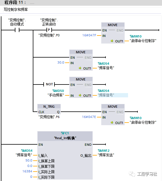
② In automatic mode, the inverter can be set to 30Hz frequency.
③ The status, frequency, DC bus voltage, and operating current of the inverter can be read; acceleration and deceleration times can be set, as shown in Figure 1-0.
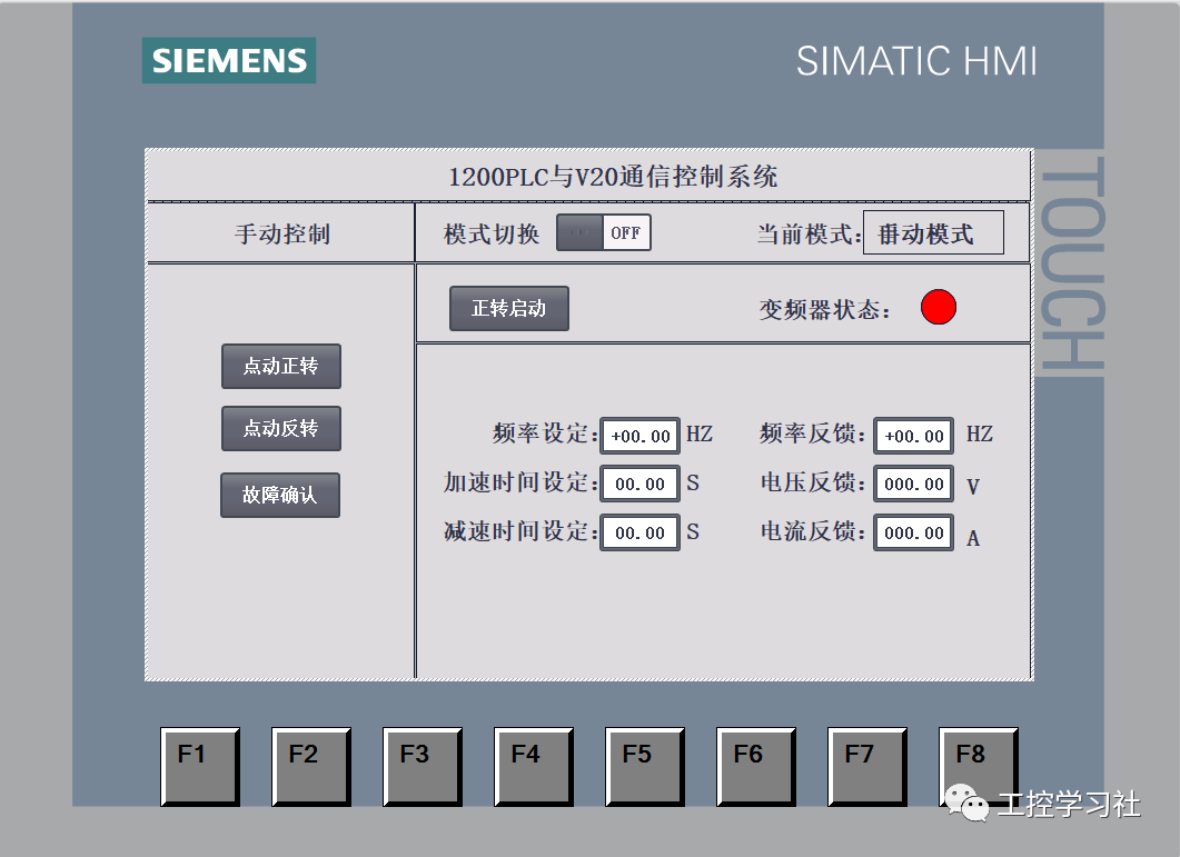
Figure 1-0
(1) Wiring, as shown in Figures 1-1 and 1-2.
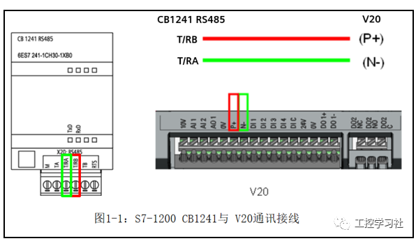
Figure 1-1
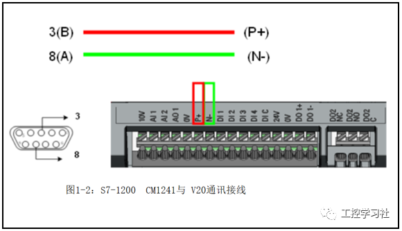
Figure 1-2
(2) Parameter Settings
Select connection macro CN011 directly on the inverter, and the default settings after selection are shown in Table 2-3.
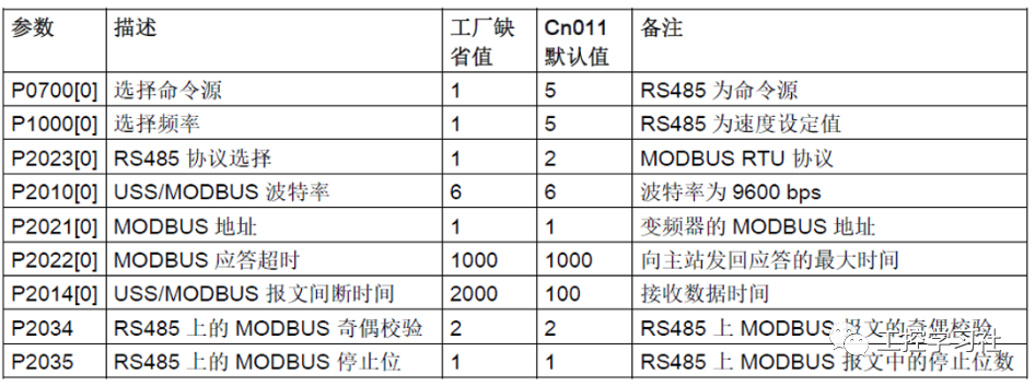
Table 2-3: Connection Macro CN011 Parameter Settings
(1) Refer to the V20 inverter manual for register descriptions, as shown in Table 2-4.
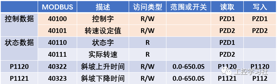
Table 2-4
(2) Control word description, as shown in Table 2-5.
This mainly explains the meaning of the value in Modbus address 40100: writing 16#047E to address 40010 represents running preparation and stop; the meanings of other values are as per the table comparison.
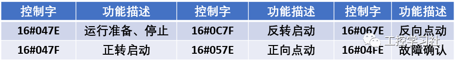
Table 2-5
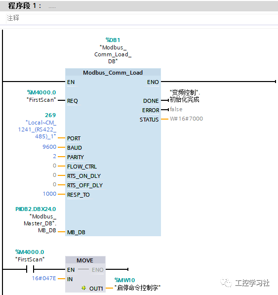
(1) OB1 Program
Program segment 1 mainly calls the Modbus initialization instruction, setting parameters such as baud rate and parity. At the same time, one scanning cycle after power-up writes the control word 16#047E to prepare for starting the inverter.
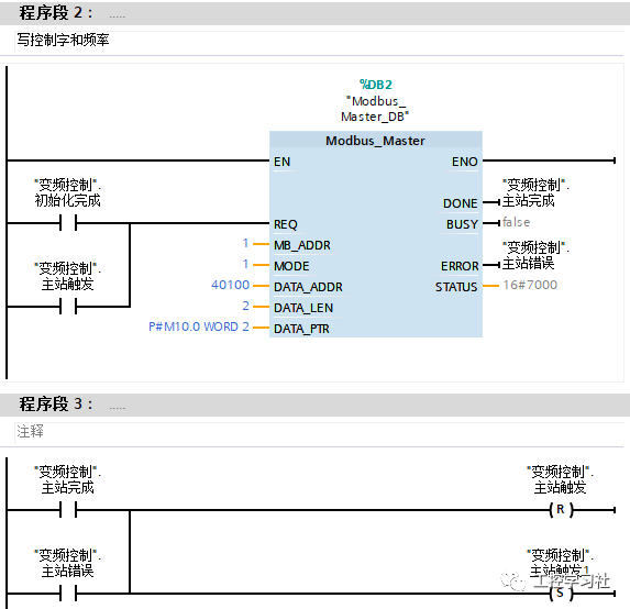
Program segment 2 mainly implements writing commands and frequency to control the inverter. Program segment 3 uses completion bits and error bits for polling; other network segment polling methods are the same.
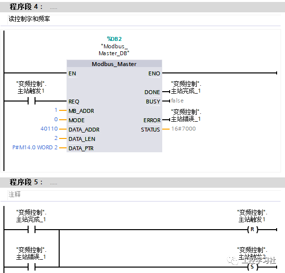
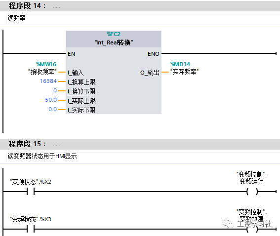
Program segment 4 implements reading the control word and frequency.
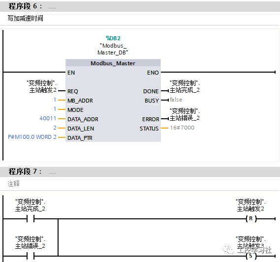
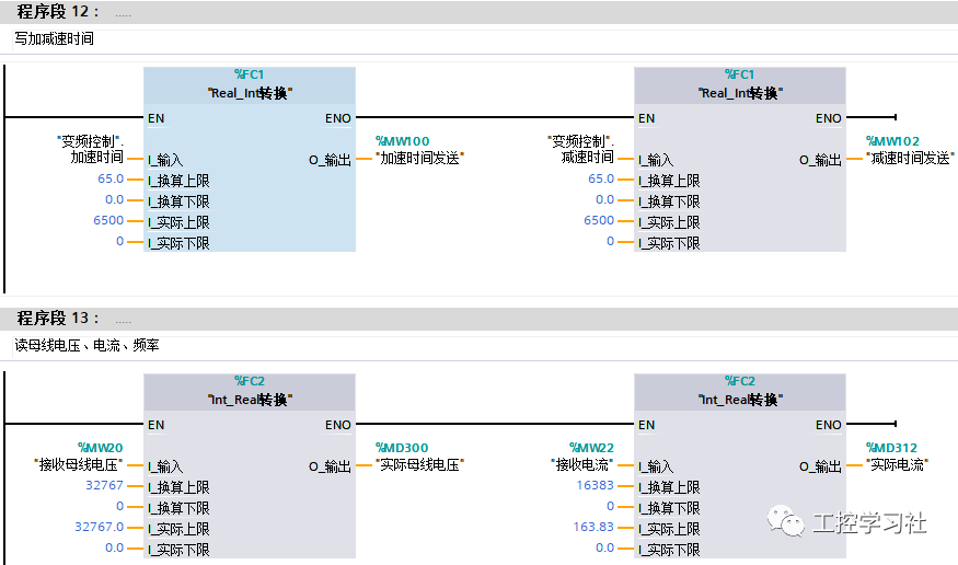
Program segment 6 implements writing the acceleration and deceleration time settings.
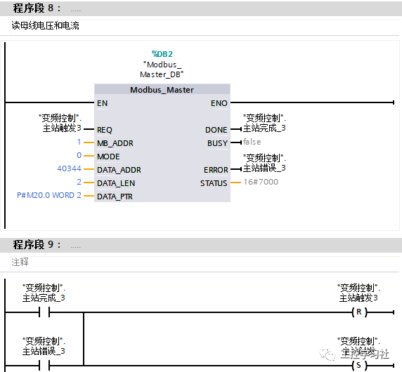
Program segment 8 implements reading the bus voltage and operating current.
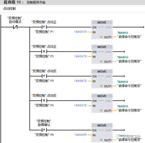
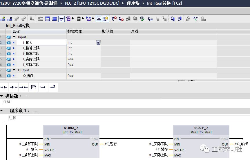
(2) FC2 Program Design
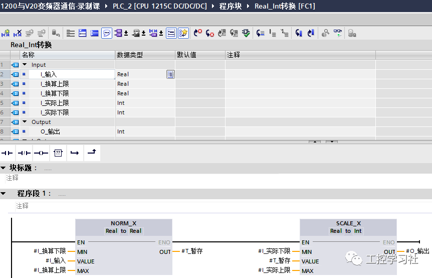
(3) FC1 Program Design
Source: Jicheng Training Network, Author: Guo Biao, Reproduction without permission is prohibited~