Click the ” Technical Training ” above to select “Pin to Top”
120,000+ followers on the industrial control WeChat platform: Technical sharing, learning exchange, industrial control videos
Good evening everyone, today I will continue to share knowledge about MODBUS communication between touch screens and inverters. Previously, I shared two steps required for communication between a touch screen and an inverter:
(1) Selection of communication driver in the touch screen
(2) Establishment of variables in the touch screen
Today we will continue to share some layout tips for touch screens and configuration in the touch screen
3. Layout and Tips for Touch Screen
When configuring Siemens touch screens, you can copy some images into the touch screen. For example, if you use text to write names in the Siemens touch screen, the font is quite uniform, and you cannot choose more fonts. This includes buttons, numeric input/output displays which are quite monotonous if only using the components provided in the touch screen software. At this point, we can consider preparing images externally and then copying screenshots into the touch screen layout, such as taking screenshots from PPT. As shown in the image below:
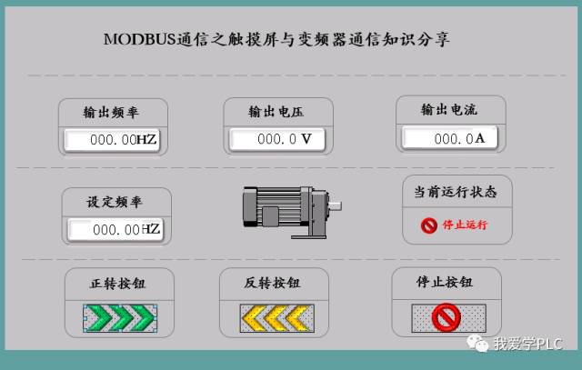
The entire screen content here is prepared in PPT, and then a screenshot is placed. When taking the screenshot, pay attention to the consistency of size.
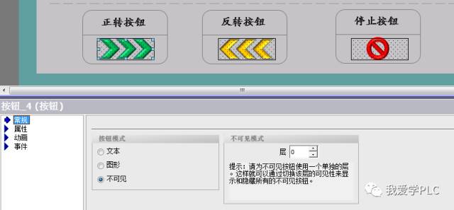
Once the screen is prepared, configure the corresponding buttons, numeric displays, and status displays as shown in the image above. For each externally prepared button, place an invisible button on top of it, and configure the button as shown in the image:
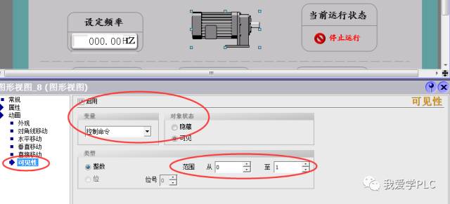
Similarly, for numeric displays, handle them in the same way. When choosing styles, you can select no style, so the data display area will not show borders. For motors, you can choose different colored motors, and in the dialog properties, configure to display different images based on the numeric values. When overlapping images, ensure that the same size and position are set for the overlap in the layout. As shown in the image, three differently colored motors are overlapped to indicate different states of the motor:
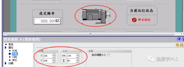
Based on different numbers in the variable, display different motors as shown in the image:
4. Variable Connection and Configuration in the Screen
In this screen, in addition to the configuration of the status displays mentioned above, the main task is to configure the forward and reverse operation of the motor, the stop button, and the input and output of frequency, voltage, and current displays.
(1) Button Configuration
Controlling the operation of the inverter requires clicking the button. After clicking the button, you need to write the corresponding command code value into the Modbus information register address of the inverter. Therefore, the operation of the button is not simply a control of the position. At this point, when selecting event functions, you cannot choose to edit the bit function as you would with PLC bit control; you should select the function for inputting numeric values, as shown in the image below:
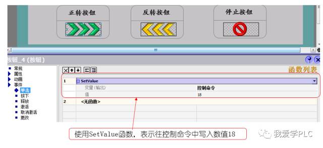
In the same manner, for the reverse and stop buttons, you only need to write different values into the control command.
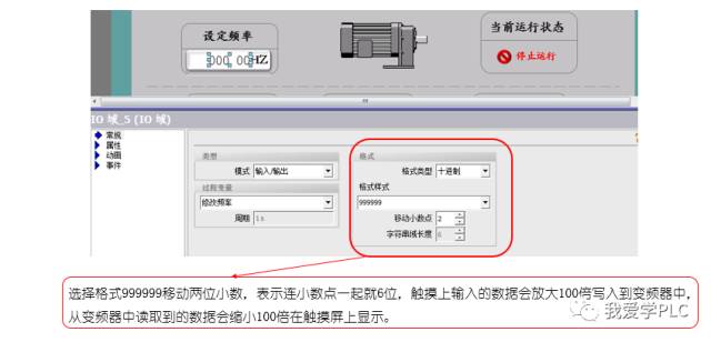
(2) Frequency and Voltage/Current Input Display Configuration.
Here, taking input frequency as an example, in a previous article, it can be seen that the input frequency has 2 decimal places, meaning the resolution of the frequency is 0.01HZ. In other words, if an input value of 3000 is entered, the input frequency would be 30.00HZ. Do we need to perform calculations on the touch screen? Should we divide the input number by 100? We can do without calculations; we only need to move the decimal point. As shown in the image:
Regarding this sharing, I hope it inspires everyone. If there are any inaccuracies, please correct me, thank you!!! The article has obtained original authorization, please contact WeChat ID I Love Learning PLC for reprint Good materials need to be shared!
Click Read the Original to learn about electrical engineering, PLC, inverter servo, CNC robots, and more
↓↓↓