Siemens 200smart Modbus RTU Communication Example
Communication Materials:
1) Two PLCs, namely the 200smart CR60 and SR20;
2) Two DP connectors (6ES7972-0BX12-0XA0)
3) Several connecting wires (for PLC power and communication)
Verification Content:
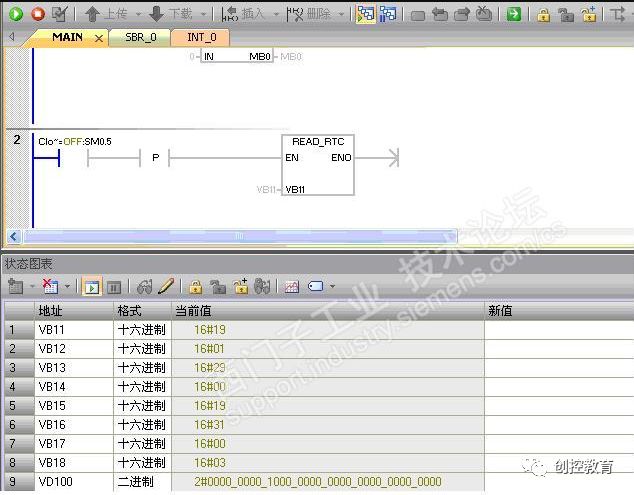
Set: CR60 PLC as the master station, sending the PLC system clock (8 bytes of information) to the SR20 slave station; the SR20 slave sends a double-word cyclic shifted data back to the master station, and the communication data VD100 is received and output to QD0.
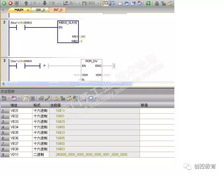
Master Station Program:
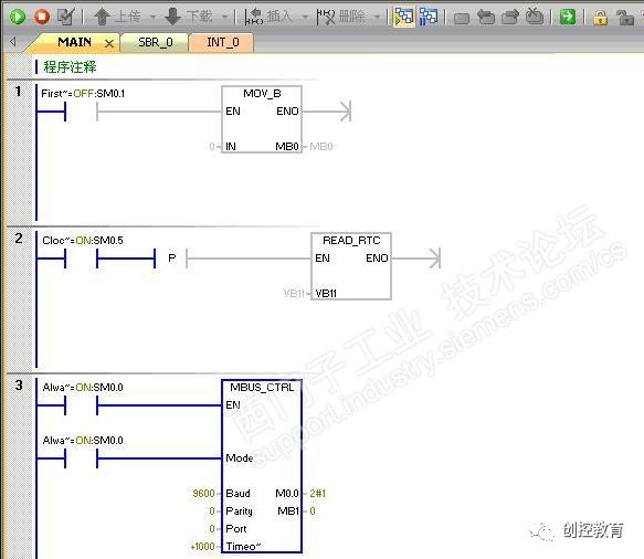
During the verification process, an error occurred where the MSG instruction always displayed 6, indicating no response from the slave station. During my verification, due to the connection between the two PLCs not confirming the 3+ and 8- connections, wiring errors occurred, causing the MSG error message to be 6. After checking, I found the reason and rewired, but the alarm still showed 6. Finally, I checked that the control program was incomplete, mainly because MB0 was not initialized, causing the error value not to refresh effectively. Thus, I added the initialization operation in program segment 1 to resolve the issue.
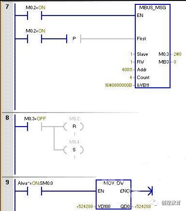

The main understanding of the master station MSG instruction is the application of the Addr address, which is described below.
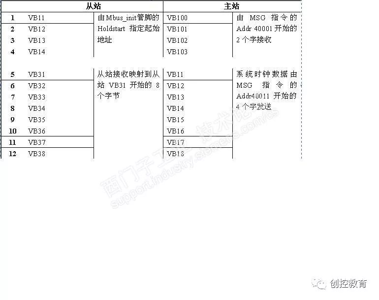
Slave Station Program: The slave communication address is set to 1#
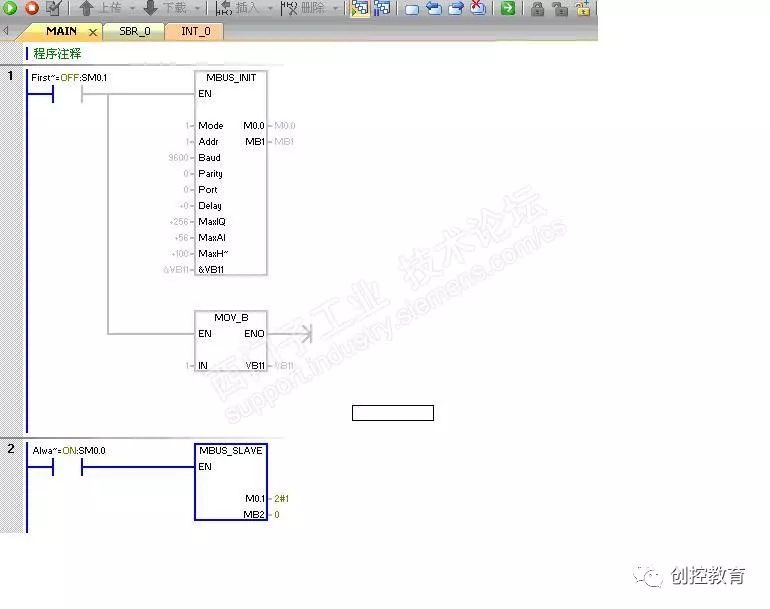
From VB31, the slave starts to read the 8 bytes of the master station system clock data starting from VB11, where the starting address of VB31 is defined by Addr address 40011. The results of the slave loop instruction VD11 will be sent and received from the starting address defined by Mbus_init’s Holdstart.
Writing Summary:
Writing the Modbus RTU communication program from simple to deep, the slave communication program is relatively simple, only specifying the communication type defined by Mbus_init pins maxIQ/maxAI/maxHOLD/Holdstart, and other pins matching according to the master station definition. The master station needs to determine based on the slave address offset.
Communication Data:
The relative difficulty of the Modbus communication program is the address mapping relationship.
The master station reads the data from the slave, and the starting address is calculated based on the starting address defined by the slave Holdstart pin, not the physical address of the slave’s V area. In the verification program, the starting address of the slave’s Mbus_init is VB11, so the master station MSG instruction’s Addr 40001 should refer to the slave’s VB11 address.
Similarly, when the slave reads the master station’s system clock, the master station’s MSG instruction’s Addr 40011 corresponds to the slave’s address, which is offset by 10 words (offset 10 word + 11 byte = 31 byte), which is stored in the 8 bytes starting from VB31. The calculation of the Modbus communication address starts from 40001.
(Content sourced from the internet, copyright belongs to the original author)
Disclaimer: If there are copyright issues, please contact for deletion! No individual or organization bears related legal responsibilities.
Recommended Reading:
Public Course Video Replay [S7-200smart and Siemens V20 Inverter MODBUS Communication]
Why Engineers Find It Hard to Get Girlfriends? Check If You Fall into This Category.
Junior vs. Senior Industrial Control Personnel
What Is It Like to Date an Electrical Engineer?
Public Course Video on Siemens S7-300/400 STL Language Indirect Addressing (16-bit Pointer, 32-bit Pointer)
How Is It Working in Industrial Control? Is It Easy? Is It Profitable? Unified Answers!