Click on the “Technical Training” above and select “Top Official Account“
Over 160,000 industrial control professionals follow this WeChat platform: technical sharing, learning exchange, industrial control videos
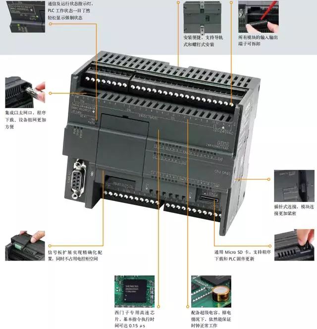
Detailed structure diagram of Siemens S7-200 SMART PLC
1. Siemens S7-200 SMART as Modbus Slave
1. Check the Micro/WIN SMART Modbus RTU Slave instruction library (Figure 1), which should include the subroutines MBUS_INIT and MBUS_SLAVE.
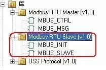
Modbus Slave library file for Siemens S7-200
Figure 1. Library instructions in the instruction tree
2. During programming, use SM0.1 to call the subroutine MBUS_INIT for initialization, and use SM0.0 to call MBUS_SLAVE, specifying the corresponding parameters. Detailed descriptions of the parameters can be found in the local variable table of the subroutine;

Detailed analysis of Modbus Slave for Siemens S7-200Figure 2.
Calling the Modbus RTU communication instruction library, the meanings of the parameters in the figure are as follows:
a. Mode selection: Start/Stop Modbus, 1=start; 0=stop
b. Slave address: Modbus slave address, range 1~247
c. Baud rate: selectable 1200, 2400, 4800, 9600, 19200, 38400, 57600, 115200
d. Parity: 0=no parity; 1=odd parity; 2=even parity
e. Port: 0=integrated RS-485 in CPU, 1=RS-485 or RS-232 on optional signal board.
f. Delay: additional delay between characters, default value is 0
g. Maximum I/Q bits: maximum I/O points participating in communication, S7-200 SMART’s I/O image area is 256/256 (currently can only connect a maximum of 4 extension modules, thus the maximum I/O points are 188/188)
h. Maximum AI words: maximum AI channels participating in communication, up to 56
i. Maximum holding register area: participating V storage area words (VW)
j. Starting address of holding register area: specified by &VBx (indirect addressing)
k. Initialization completion flag: set to 1 after successful initialization
l. Initialization error code
m. Modbus execution: set to 1 during communication, 0 when there is no Modbus communication activity.
n. Error code: 0=no error
3. Allocate library instruction data area (Library Memory) in the CPU’s V data area. The Modbus Slave instruction library requires a global V storage area of 781 bytes. Calling the STEP 7 – Micro/WIN SMART Instruction Library (instruction library) requires allocating a library instruction data area (Library Memory). The library instruction data area is the variable storage space needed by the corresponding library’s subroutines and interrupt programs. If the library instruction data area is not allocated during programming, many identical errors will occur during compilation.
Operating Steps:
1) In the instruction tree of the Project, right-click on Program Block, and select Library Memory from the pop-up shortcut menu, as shown in Figure 3:
Allocate Address RegisterFigure 3.
“Library Memory” button 2) In the pop-up tab, set the library instruction data area, as shown in Figure 4:
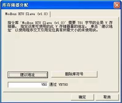
Siemens S7-200 library memoryFigure 4.
By default, it starts from VB0, but ensure that the address range of this memory does not overlap with the addresses used by other programs. The “Suggest Address” button can also auto-allocate.If necessary, use the master station software for testing
Note:The holding register area specified by the subroutine parameters HoldStart and MaxHold is allocated in the V data storage area of the S7-200 SMART CPU, and this data area must not overlap with the library instruction data area; otherwise, errors will occur during runtime, and communication will not function properly. Note that the holding register area in Modbus is addressed by “words”, meaning that MaxHold specifies the number of VW rather than VB.
In the example in Figure 2, the Modbus holding register area is specified to start from VB1000 (HoldStart = VB1000), and the holding register is 1000 words (MaxHold=1000). Since the holding register is in words (two bytes), this communication buffer actually occupies VB1000 to VB2999, totaling 2000 bytes. Therefore, when allocating the library instruction reserved data area, it is essential to avoid the range of VB1000 to VB2999.
Note:The size of the V storage area of the CPU you choose! The size of the V data storage area varies with different CPU models. You should select the size of the Modbus holding register area according to your needs.
After compiling the project containing the Modbus RTU Slave instruction library and downloading it to the CPU, running some Modbus testing software on the programming computer (PG/PC) can verify whether the Modbus RTU communication of the S7-200 SMART CPU is normal, which is useful for troubleshooting. The testing software connects to the CPU via the computer’s serial port (RS-232) and the PC/PPI cable. If necessary, the PC/PPI cable must be set to free port communication mode.
2. Modbus RTU Slave Example
Siemens S7-200 Modbus communication engineering example
The Modbus RTU Slave address corresponds to the address of S7-200 SMART: Modbus addresses always appear in the form of 00001, 30004, etc. The internal data storage area of the S7-200 SMART CPU corresponds to the four types of Modbus addresses: 0, 1, 3, and 4 as follows:
Where T is the starting address of the buffer in the S7-200 SMART CPU, which is HoldStart.
If the V storage area address in the S7-200 SMART CPU is known, the formula for calculating the Modbus address is as follows:
Modbus Address = 40000 + (T/2+1); T is even
The Modbus RTU Slave instruction library supports specific Modbus functions. The master station using this instruction library must comply with the requirements of this instruction library.
3. Conclusion
Both parties in communication must simultaneously support one of the modes mentioned above. Modbus is a master/slave communication mode with a single master station. There can only be one master station on the Modbus network, which has no address, while the address range for slaves is 0 – 247, where 0 is the broadcast address, and the actual address range for slaves is 1 – 247.
The Modbus communication standard protocol can be transmitted through various transmission methods, such as RS232C, RS485, fiber optics, radio, etc. The communication port on the S7-200 CPU implements RS485 half-duplex communication, using the free port function of the S7-200 SMART.
Share with friends, let’s learn together!
ClickRead Original to learn about electrical engineering, PLC, frequency servo, CNC robots, and more.