1. Introduction
Modbus communication is a widely used communication protocol, commonly applied in frequency converters, smart instruments, and other intelligent devices. This article uses the S7-1200 series PLC as the Modbus master and the Omron E5EZ smart temperature controller as the slave, demonstrating how to read the current temperature value and modify the set temperature value using the SCL programming language.
2. Hardware Selection and Instrument Communication Parameter Settings
(1) Hardware Selection
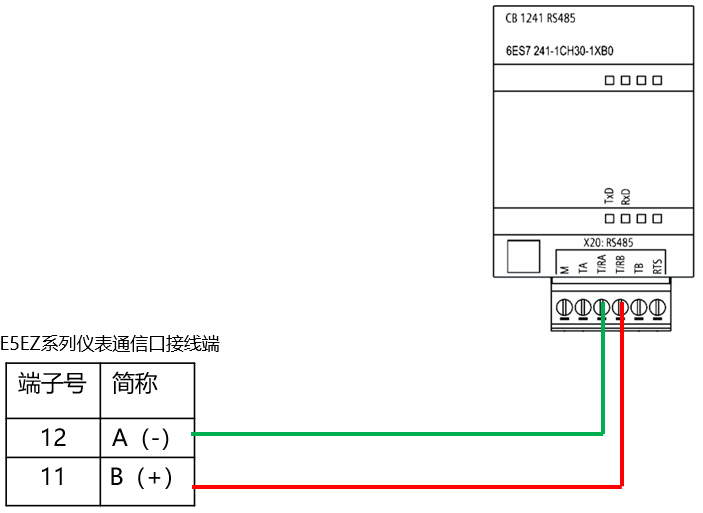
In this case, the S7-1200 PLC is selected with CPU model CPU1214C, RS485 communication interface, and communication board CB1241. The Omron smart instrument is the Omron E5EZ model. The wiring between the PLC communication signal board and the Omron smart instrument is shown in the figure below:
(2) Instrument Communication Parameter SettingsThe main communication parameters for the instrument are shown in the figure below, which include protocol selection, station number settings, baud rate, data bits, and parity bits.
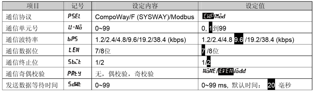
üProtocol selection: Modbus communication protocol, select Mod on the instrument.
üCommunication unit number (station number), set to 01.
üBaud rate setting, set to 9.6, indicating 9600 bps.
üData bits, set to 8 data bits.
üStop bits, set to 1 stop bit.
üParity, set to EVEN (even parity).
3. Communication Program Development
(1) Address Calculation
According to the communication manual of the Omron E5EZ instrument regarding the Modbus communication data query table, the data address for the PV value is 0404H, with a size of 32 bits, and the address for the set temperature value is 0106H, also with a size of 32 bits, as indicated in the index:

According to the S7-1200 Modbus communication instruction, the address is defined using the Modbus register address. Therefore, after conversion, the PV value’s Modbus register address is 41029 in decimal, and the set temperature value’s Modbus register address is 40263 in decimal.
Note: There are mainly four types of Modbus register addresses: 0XXXX type, indicating read/write to coils; 1XXXX type, indicating reading of discrete inputs; 3XXXX, indicating reading of input registers (corresponding to Modbus function code 04); and 4XXXX indicating read/write operations on holding registers (corresponding to function codes 06, 03, 16).The calculation method is to convert the corresponding hexadecimal data address to decimal, add 1, and then prepend the result with the number 4 to indicate the corresponding type.
(2) Create Communication Data Block DB1000
Create a data block DB1000, define communication-related variables in this data block, and assign the corresponding communication values to the variables, as shown in the figure below:
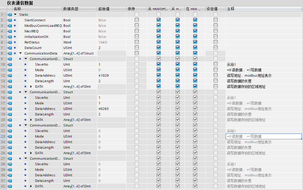
Among them, the definition structure of the variable CommunicationData is defined according to the communication instruction “Modbus_Master” pin, and the number of array elements can be modified based on the amount of communication data to be debugged.
(3) Create Communication Program Block FB1000Create an FB block and name it “Instrument Communication Program”. The programming language selected for this block is SCL, and the interface variables are established as shown in the figure below:
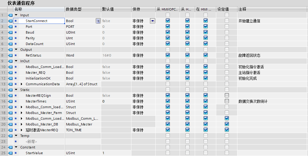
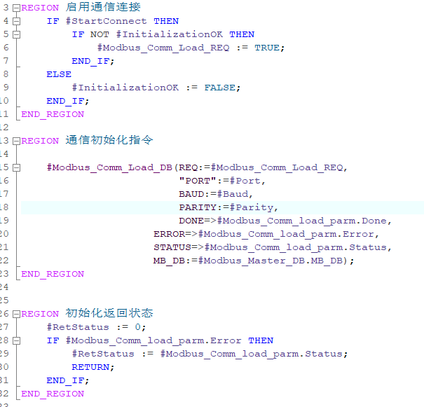
Enable the communication connection and call the communication port initialization operation program.
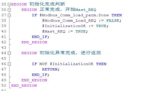
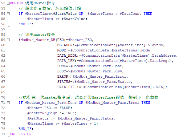
Call the Mast instruction to complete data exchange and change the program that needs to send data.
In the OB block, call this communication program and assign the corresponding actual parameters to the interface of this communication program.
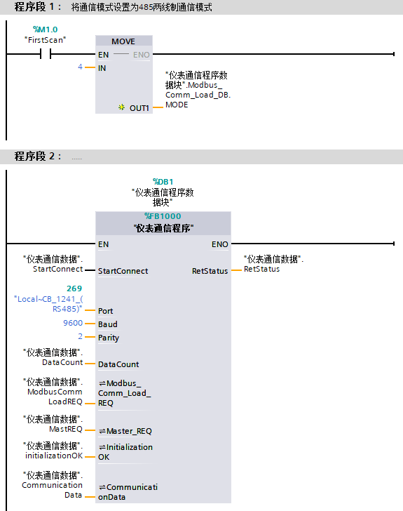
4. Conclusion
In this case, it is important to note:(1) Modify the mode in the initial instruction, and when the first scan bit is connected, send 4 to the “Modbus_Comm_Load_DB.MODE” variable.(2) If the elements of the CommunicationData variable start from 0, then the value of the constant StartValue defined in the interface area of the communication program FB block should be set to 0.(3) If the number of communications increases, the number of elements in the CommunicationData variable can be modified, and the relevant data for the elements can be defined, then specify the number of communication data in DataCount without needing to adjust the communication program.
Scan the QR code below to receive more communication cases. If you need other types of communication cases, please leave a message in the comments. Thank you!