About Us: Qicheng Automation Training, China’s leading industrial robot training service provider.
Training Programs:Robotics + PLC System Integration + Motion Control + Robotics + Machine Vision
The Modbus protocol is arguably the most widely used communication protocol in the field of industrial automation. Its openness, expandability, and standardization make it a universal industrial standard. With it, products from different manufacturers can be easily and reliably integrated into the network, enabling centralized monitoring and decentralized control functions.
Currently, the main Modbus specifications used are ASCII, RTU, TCP, etc., without specifying the physical layer. The commonly used interface forms for Modbus include RS-232C, RS485, RS422, and also RJ45 interfaces. The Modbus ASCII and RTU protocols specify the message, data structure, commands, and response methods based on these interfaces. Modbus data communication adopts a Master/Slave mode, where the Master sends a data request message, and upon receiving the correct message, the Slave can send data back to the Master in response to the request; the Master can also directly send messages to modify the Slave’s data, achieving bidirectional read/write.

In serial communication, the “baud rate” describes the data transmission rate. An international standard baud rate series is defined: 110, 300, 600, 1200, 1800, 2400, 4800, 9600, 14.4Kbps, 19.2Kbps, 28.8Kbps, 33.6Kbps, 56Kbps. For example, 9600bps indicates that 9600 bits are transmitted per second, including the bits for characters and other necessary bits such as start bits, stop bits, and parity bits.
In the field of automation, we often use the RTU mode. The format of each byte in RTU mode is as follows:
Encoding system: 8-bit binary, hexadecimal 0-9, A-F
Data bits: 1 start bit
8 data bits, sent in low order first
1 bit for odd/even parity; 0 bits if no parity
1 stop bit with parity; 2 stop bits without parity
Error check area: Cyclic Redundancy Check (CRC)
Slave address setting: The information address includes 2 characters (ASCII) or 8 bits (RTU), valid slave device addresses range from 0-247 (decimal).
Function code setting: The information frame function code includes characters (ASCII) or 8 bits (RTU). Valid code range is 1-225 (decimal);
Data area content: The data area has 2 hexadecimal data bits, data range is 00-FF (hexadecimal). Depending on the serial transmission method, the data area can consist of a pair of ASCII characters or a single RTU character.
Message frame in RTU mode:

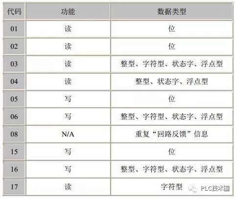
Modbus function codes:

Modbus function codes and data type correspondence table:
Example of reading complete data in RTU mode:
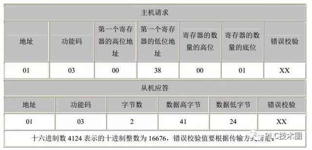
Let’s analyze: The host sends a command to access the slave address 1, using function code 03 (read holding register), with the high 8 bits and low 8 bits of the starting address indicating the starting address of the analog quantity to be read (the starting address is 0). For example, the starting address in this example is 38, which is 56 in decimal. The number of registers high 8 bits and low 8 bits indicates how many analog quantities to read starting from the starting address. In this example, it is 1 analog quantity. Note that in the returned information, one analog quantity needs to return two bytes. The error check is CRC check.
Slave response: The device address and command number are the same as above. The returned byte count indicates the number of data bytes, which is the value of n in data 1, 2…n. In this example, 1 analog quantity data is returned, and since one analog quantity requires 2 bytes, a total of 2 bytes are returned. The high and low bytes of data: 41 and 24 represent the value of the returned analog quantity, which is 16676 in decimal. The error check is CRC check.
Further Reading
◆
◐◑ Thought-provoking! Comparison of the survival status of small and medium-sized enterprises in Germany and China
◆
◐◑ Foxconn plans to assemble 1 million robots; what is Terry Gou thinking?
◆
◐◑ S7-300/400 Advanced Notes: Cycle Processing Methods of PLC Programs and Related Content Overview
◆
◐◑ A chart to understand the top ten well-known industrial robot brands in China, worth collecting!
◆
◐◑ Now I will tell you what collaborative robots are.
About Qicheng Automation Training
About Us: Qicheng Automation Training, China’s leading industrial robot training service provider.
Contact Number:0755-33160617 33160627
Training Programs:Robotics + PLC System Integration + Motion Control + Robotics + Machine Vision
Special Services:3000 square meter training center + job placement assistance + industry-leading curriculum

Add WeChat to learn about class details