Click 👆 above to follow Engineer Yan Ji and ★star★.

Protocol Definition
- 1. Modbus is a request-response protocol implemented using a master-slave relationship.
- 2. The Modbus protocol introduces different application data units to change the packet format used in serial communication or to allow the use of TCP/IP and User Datagram Protocol (UDP) networks. Its communication protocol is also relatively simple, with the frame structure as follows (ADU contains PDU): ADU: Application Data Unit PDU: Protocol Data Unit
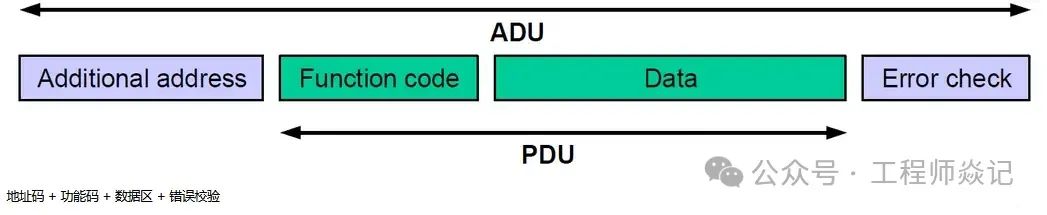
Protocol Data Unit PDU (Function Code and Data)
- • PDU (Packet Data Unit) and its processing codes form the core of the Modbus application protocol specification.
- • The Modbus PDU format is defined as a function code followed by a set of associated data. The size and content of this data are defined by the function code, and the total size of the PDU (function code and data) cannot exceed 253 bytes. Each function code has a specific behavior, and the slave device can flexibly implement these behaviors based on the required application behavior.
- • The slave device will validate inputs such as function code, data address, and data range. It then performs the requested operation and sends a response that corresponds to the code. If any step in this process fails, an exception will be returned to the requester.

- • The PDU consists of a single-byte function code followed by up to 252 bytes of data specific to the function.
- • The function code is the first item that needs to be validated. If the function code is not recognized by the requested device, it will respond with an exception. If the function code is accepted, the slave device will begin to parse the data according to the function definition.
Data Types
There are four types of Modbus operation objects: coil status, discrete input, holding register, and input register.
- • Coil: Output bit of the PLC, discrete, readable and writable in MODBUS (e.g., outputting high or low level of an I/O)
- • Discrete Input: Input bit of the PLC, discrete, read-only in MODBUS (e.g., the state of a button)
- • Input Register: A register that can only be changed from the analog input side in the PLC, read-only in MODBUS (e.g., temperature value)
- • Holding Register: A register used for outputting analog signals in the PLC, readable and writable in MODBUS (e.g., output values of multiple I/Os)
These databases define the type and access rights of the data contained. The slave device can directly access this data as it is hosted locally by the device. The data accessible via Modbus is typically a subset of the device’s main memory. In contrast, the Modbus master device must request access to this data through various function codes.

These blocks allow you to restrict or allow access to different data elements and provide a simplified mechanism for the application layer to access different data types. These blocks are entirely conceptual. They may exist as independent memory addresses in a given system but may also overlap. For example, coil status 1 may exist in the same memory as the first bit represented by holding register 1. The addressing scheme is entirely defined by the slave device, and its interpretation of each memory area is an important part of the device data model.
Data Model Addressing
The specification defines each block as containing an address space of up to 65,536 (216) elements. In the definition of the PDU, Modbus defines the address of each data element, ranging from 0 to 65,535. However, the numbering of each data element ranges from 1 to n, where n’s maximum value is 65,536. That is, coil status 1 is located at address 0 in the coil status block, while holding register 54 is located at address 53 in the memory section defined as holding registers by the slave. The full range allowed by the specification does not need to be implemented by a given device. For example, a device may choose not to implement coils, discrete inputs, or input registers, but only use holding registers 150 to 175 and 200 to 225. This is entirely acceptable and invalid access attempts are handled through exceptions.
Data Addressing Range
Although the specification defines different data types as existing in different blocks and assigns a local address range for each type, this does not necessarily translate into an intuitive addressing scheme for recording or understanding the Modbus-accessible memory of a given device. To simplify the understanding of memory block locations, a numbering scheme is introduced that adds a prefix to the address of the data in question. For example, the device manual will not refer to the data item at address 13 register 14, but rather to the data item at address 4,014,40,014 or 400,014. In any case, the first digit is 4, indicating a holding register, while the remaining digits specify the address. The distinction between 4XXX, 4XXXX, and 4XXXXX depends on the address space used by the device. If all 65,536 registers are in use, the 4XXXXX notation should be used, as it allows a range of 400,001~465,536. If only a few registers are used, the common practice is to use the range 4,001 to 4,999. In this addressing scheme, each data type is assigned a prefix:

Coil status has a prefix of 0. This means that a reference to 4001 may refer to either holding register 1 or coil 4001. Therefore, it is recommended that all new addressing schemes adopt a 6-digit addressing with leading zeros and be documented accordingly. Thus, the address of holding register 1 is 400,001, while the address of coil 4001 is 004,001.
Data Address Starting Value
The difference between memory addresses and reference numbers is further complicated by the index chosen by the given application. As mentioned earlier, holding register 1 is located at address zero. Typically, the reference number is indexed from 1, meaning the starting value of a given range is 1. Therefore, 400,001 is represented as holding register 00001 at address 0. Some practices choose to start their ranges at zero, meaning 400,000 translates to holding register at address zero. Below is the register indexing scheme, with 1-indexed ranges being more widely applied and strongly recommended.

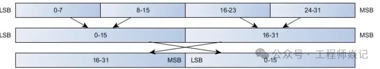
Big Endian and Little Endian Data
Multi-register data (single precision floating point values) can be easily transmitted in Modbus by splitting the data into two registers. Since this is not defined by the standard, the order of the split bytes is not specified. Although each unsigned word must be sent in network (big-endian) byte order to meet the standard, many devices reverse the byte order of multi-byte data. The following diagram shows an uncommon but valid example.
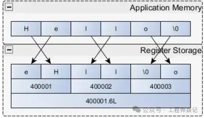
Strings can be easily stored in Modbus registers. For simplicity, some methods require the string length to be a multiple of 2 and use control to fill the extra space. The byte order is also a variable in string interactions. The string format may or may not include NULL as the final value.
Modbus Function Codes
Depending on the object, the Modbus function codes are as follows:
| Function Code | Name | Function |
| 01 | Read Coil Status | Get the current status of a set of logical coils (ON/OFF) |
| 02 | Read Input Status | Get the current status of a set of switch inputs (ON/OFF) |
| 03 | Read Holding Registers | Get the current binary value in one or more holding registers |
| 04 | Read Input Registers | Get the current binary value in one or more input registers |
| 05 | Force Single Coil | Force the ON/OFF state of a logical coil |
| 06 | Preset Single Register | Load a specific binary value into a holding register |
| 07 | Read Exception Status | Get the ON/OFF status of 8 internal coils, the addressing of these 8 coils is determined by the controller, user logic can define these coils to indicate slave status, short messages are suitable for quickly reading status |
| 08 | Return Diagnostic Sub-Function | Send a diagnostic check message to the slave to evaluate communication processing |
| 09 | Programming (only for 484) | Simulate the programming function of the host to modify the PC slave logic |
| 10 | Inquiry (only for 484) | Allows the host to communicate with a slave performing a long program task, inquiring whether the slave has completed its operation task, this function code is only sent after a message containing function code 9 is sent |
| 11 | Read Event Count | Allows the host to issue a single inquiry and immediately determine whether the operation was successful, especially when the command or other response generates a communication error |
| 12 | Read Communication Event Log | Allows the host to retrieve the ModBus transaction communication event log for each slave. If a transaction is completed, the log will provide information about errors |
| 13 | Programming (184/384 484 584) | Simulate the programming function to modify the PC slave logic |
| 14 | Inquiry (184/384 484 584) | Allows the host to communicate with a slave performing a task, periodically inquiring whether the slave has completed its program operation, this function code can only be sent after a message containing function code 13 is sent |
| 15 | Force Multiple Coils | Force the ON/OFF state of a series of consecutive logical coils |
| 16 | Preset Multiple Registers | Load specific binary values into a series of consecutive holding registers |
| 17 | Report Slave Identification | Allows the host to determine the type of addressed slave and the status of the slave’s running indicator |
| 18 | (884 and micro 84) | Simulate programming function to modify PC status logic |
| 19 | Reset Communication Link | After a non-modifiable error occurs, reset the slave to a known state, can reset the sequence byte |
| 20 | Read General Parameters (584L) | Display data information in the extended memory file |
| 21 | Write General Parameters (584L) | Write or modify general parameters in the extended storage file |
| 22-64 | Reserved for user functions | |
| 65-72 | Reserved for user functions | Reserved for user function expansion coding |
| 73-199 | Illegal Function | |
| 120-127 | Reserved | Reserved for internal use |
| 128-255 | Reserved | Reserved for exception handling |
If this article is helpful to you, please follow for more exciting content!Disclaimer: The articles pushed are for readers’ learning and communication purposes only. The copyright of the articles, images, etc. belongs to the original author, and original works are for reference only. Plagiarists will be pursued, and if there is any infringement, please contact for deletion.If you like the article, please give a “like” or “share” so we can progress together!