
Understanding the CAN Communication Bus:
With the rapid development of the times, automotive electronic technology is constantly updated, so we must improve our technical level through continuous learning. In this issue, we will explore the automotive CAN communication bus, covering the principles, design, applications, and maintenance of CAN in a comprehensive article!
“What is a CAN Bus?”
No matter how many electronic control units a vehicle has, regardless of the information capacity, each electronic control unit only needs to connect two wires to two nodes. These two wires are called the data bus, also known as the BUS line. The entire network is called CAN, which stands for Controller Area Network, meaning that control units exchange data through the network.
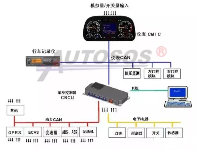
Introduction to CAN-BUS
Bus System:

Vehicle Communication CAN Bus:
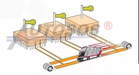
To make an analogy: The bus system, also known as CAN-BUS, works similarly to a public bus. Each stop is equivalent to a control unit, while the bus route represents the CAN bus, where data is transmitted instead of passengers. When a control unit receives information from a sensor responsible for sending data to it, it processes this information and takes corresponding actions, sending this information onto the bus system. This information will be transmitted on the bus system, and every control unit connected to the bus system will receive it. If the information is useful, it will be stored; if not, it will be ignored.
Communication Principles of CAN Bus
The first method:『Each piece of information is exchanged through its own independent data line』
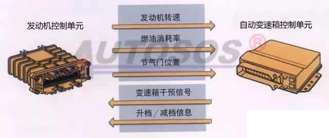
Currently, there are two forms of information transmission used in vehicles. The first method is that each piece of information is exchanged through its own independent data line. For example, if there are five types of information that need to be transmitted between two control units, then five independent data lines are required. This means that the more types of information there are, the more data lines and control unit pins will increase accordingly. These complex and numerous wiring harnesses undoubtedly increase the weight of the vehicle and pose certain difficulties for the overall wiring of the vehicle.
The second method:『All information is exchanged through two data lines』
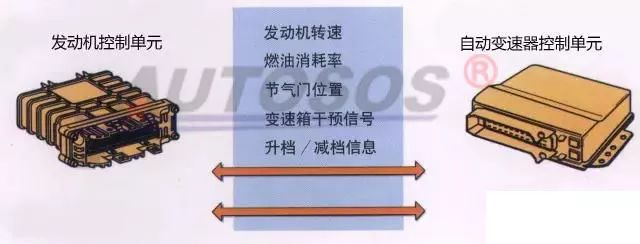
The second method is that all information between control units is exchanged through two data lines, which are also called CAN data bus. Through this method, all information, regardless of its size, can be transmitted through these two data lines, which significantly improves the overall system efficiency. A common computer keyboard has 104 keys but can issue hundreds of different commands, yet the data connection line between the keyboard and the computer host only has seven wires. The keyboard relies on different coded signals on these seven data connection lines to transmit information. The principle of the CAN data bus is similar. This switch from a dedicated line to a multi-use line can greatly reduce the number of wires in the vehicle while simplifying the overall wiring.
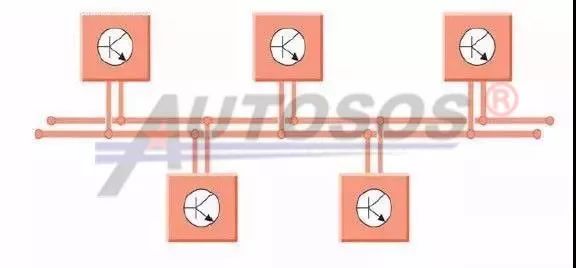
Once we understand that two control units exchange information through two data lines, we can extrapolate that the communication between multiple control units is essentially connecting each control unit to these two CAN buses, thus achieving information sharing among multiple control units.
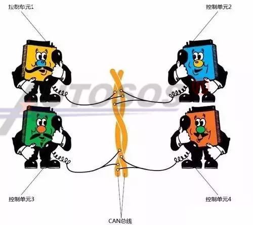
The entire principle is very similar to how a conference call operates: one phone user (control unit) “speaks” data into the network, and other users “listen” to this data. Users interested in this data will utilize it, while others will choose to ignore it.
Design of CAN Communication
1. Why are there two twisted pairs of wires in CAN?
To clarify, CAN wires are represented in single colors: the CAN-High wire is always yellow, and the CAN-Low wire is always green. (The specific colors of CAN wires depend on the vehicle manufacturer’s design, generally well distinguished from other vehicle wiring.)
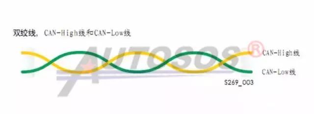
The two wires of the CAN data bus are called CAN-High and CAN-Low. The two twisted wires are called a twisted pair.
In principle, one wire is sufficient to meet the functional requirements of the CAN bus, but the system is equipped with a second wire. On this second wire, the signal voltage mirrors that of the first wire, effectively suppressing external interference.
2. Why is the CAN bus designed with high and low voltages?
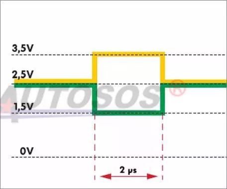
CAN Data Bus: Used for transmitting data, the data line is divided into CAN-High and CAN-Low. Data is sent to each control unit without a designated receiver; upon reception, each control unit processes the data. To prevent external electromagnetic interference and radiation, the CAN bus uses two wires twisted together, with opposite potentials on each line. During operation, the CAN high voltage is 2.5V-3.5V, and the CAN low voltage is 1.5V-2.5V. In static measurements, the CAN high voltage is about 2.6V, and the CAN low voltage is about 2.4V. This method protects the CAN bus from external electromagnetic field interference while maintaining neutrality, meaning no radiation.
What is a Communication Protocol?
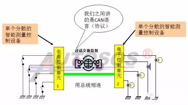
It is the principle followed when electronic control units exchange information. In simple terms, for the electronic control units in the network to communicate smoothly, they must speak the same language; the protocol is equivalent to the language. For example, the commonly used CAN bus design for commercial vehicles is based on the J1939 protocol.
Comparison of Traditional Wiring and CAN Communication Bus
1. Traditional Wiring:
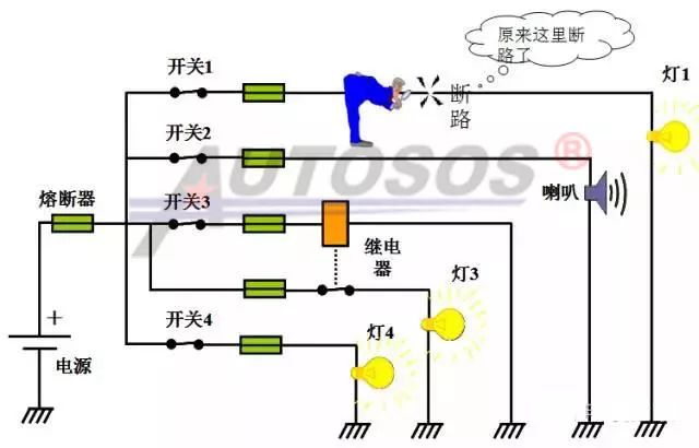
In traditional electrical control systems, there are many electrical components; each additional component adds a potential fault point. If functionality needs to be added or changed, it involves modifying the wiring harness, changing switches, or installing relays, making modifications cumbersome. If complex functions such as engine fault display in Chinese or cruise control are required, they are impossible to achieve.
2. CAN Communication Bus:
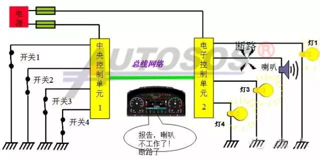
Advantages of the CAN Bus:
1> The bus control system replaces traditional fuses and relays, reducing the number of components and thus minimizing potential fault points.
2> The bus control system reduces the length of the wiring harness; longer harnesses are more prone to faults. Shortening vehicle wiring further saves costs. Due to the use of bus technology, signal transmission between modules only requires two signal wires. Wiring is localized, eliminating the need for all other wires running across the vehicle, saving wiring costs. Additionally, data sharing also reduces wiring harnesses.
3> When a fault occurs in one path of the electrical system, the electronic control module will display this fault on the instrument, facilitating repairs.
4> It meets the complex communication needs between more computer modules, with higher efficiency.
5> It has strong expandability, allowing for quick product upgrades and saving on new product development costs. CAN nodes can almost be added without modifying the existing wiring harness.
Why are Resistors Installed at Both Ends of the CAN Bus?
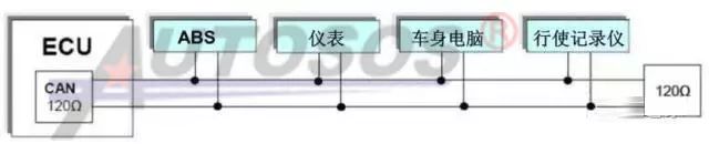
Terminal resistors are designed and installed at both ends of the automotive CAN bus!
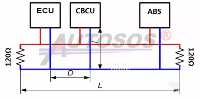
1. As shown in the diagram below, if the ECU itself does not have a 120Ω resistor, then two 120Ω resistors must be installed in parallel at both ends of the CAN network:
2. Some CAN buses have built-in resistors at the ends, as shown in the diagram (taking the DeLong natural gas CAN bus as an example):
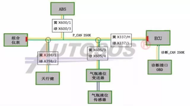
The function of terminal resistors: The data transmission terminal is a resistor that prevents data from reflecting back at the end of transmission, which would create reflected waves and damage the data, affecting CAN network data transmission. Therefore, terminal resistors are designed and installed in the CAN bus.
What is a CAN Communication Node?
1. The CAN communication bus enables information sharing between ECU, CBCU, ABS, CAN instruments, and other CAN devices, such as water temperature and oil pressure. Only the ECU needs to install the sensor to transmit the current measured water temperature and oil pressure to the CAN instrument in real-time. The CAN instrument does not need to install separate water temperature and oil pressure sensors.
2. Only CAN devices can use the CAN bus. Sometimes a vehicle has several CAN devices, such as ECU, CAN instruments, NOx sensors, etc. Each CAN device is referred to as a node, with the ECU being Node A.
3. In our maintenance work, a common fault “CAN node A bus error” does not necessarily mean a fault in the ECU itself; it is usually caused by abnormal voltage in the entire vehicle CAN network or other CAN control faults leading to CAN network interference.
Common Fault Diagnosis of CAN Bus
1、Common Fault: CAN High Shorted to Power
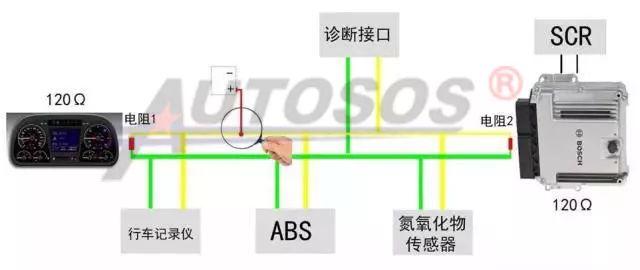
1> Turn the ignition switch to the ON position, powering all nodes in the vehicle;
2> Set the multimeter to the voltage range;
3> Connect the positive lead of the multimeter to the diagnostic interface pin CAN_H and the negative lead to ground (GND), testing the CAN-H voltage: If the voltage value is around 2.6V, it indicates normal; if the voltage value is greater than 5V or the battery voltage, it indicates that CAN-H is shorted to high power;
2. Common Fault: CAN Low Shorted to Power
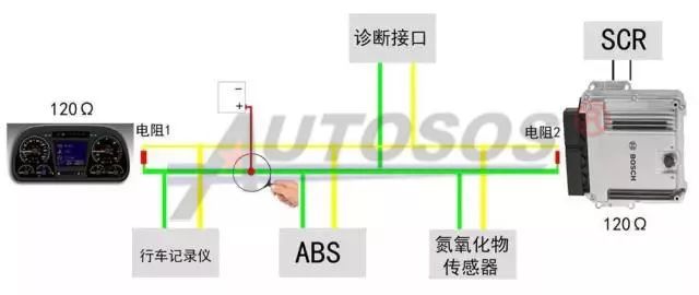
1> Turn the ignition switch to the ON position, powering all nodes in the vehicle;
2> Set the multimeter to the voltage range;
3> Connect the positive lead of the multimeter to the diagnostic interface pin CAN_L and the negative lead to ground (GND), testing the CAN-L voltage: If the voltage value is around 2.4V, it indicates normal; if the voltage value is greater than 5V or the battery voltage, it indicates that CAN-L is shorted to high power;
3. Common Fault: CAN High Shorted to Ground
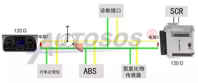
1> Disconnect the positive terminal of the battery, cutting power to the vehicle;
2> Set the multimeter to the resistance range;
3> Connect the positive lead of the multimeter to the diagnostic interface pin CAN_H and the negative lead to ground (GND), testing the resistance of CAN-H to ground. If the resistance value is greater than 100KΩ, it is normal. If the resistance value is too low, it indicates a short circuit of the CAN high line to ground.
4. Common Fault: CAN Low Shorted to Ground
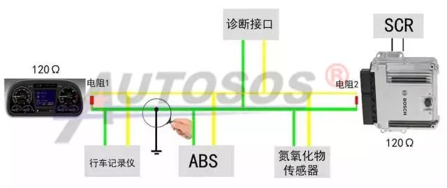
1> Disconnect the positive terminal of the battery, cutting power to the vehicle;
2> Set the multimeter to the resistance range;
3> Connect the positive lead of the multimeter to the diagnostic interface pin CAN_L and the negative lead to ground (GND), testing the resistance of CAN-L to ground. If the resistance value is greater than 100KΩ, it is normal. If the resistance value is too low, it indicates a short circuit of the CAN low line to ground.
5. Common Fault: Short Circuit Between CAN High and CAN Low Lines
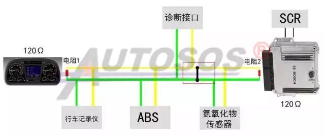
1> Disconnect the positive terminal of the battery, cutting power to the vehicle;
2> Set the multimeter to the resistance range;
3> Connect the two leads of the multimeter to the diagnostic interface pins CAN_H and CAN_L, testing whether CAN-H and CAN-L are shorted. The entire CAN bus is equipped with 120Ω resistors in parallel; under normal conditions, the measured resistance between CAN high and CAN low should be around 60Ω. If the result is abnormal, check for short circuits or open circuits in the CAN high and low lines.
Note: Another possibility is that the terminal resistors (either internal to the computer or external resistors) are malfunctioning, leading to resistance values between CAN high and CAN low that are not around 60Ω.
Note: If the above tests show no anomalies but the instrument still reports a bus communication fault, this belongs to a special fault situation. Based on experience, the following faults may occur:
1. A power disconnection in a certain node, resulting in no messages being sent.
2. A certain node not meeting the 250kbps communication rate.
3. An internal fault occurring in a certain node.
Case 1
Tianlong Instrument Displays: Instrument Did Not Receive EECU Message
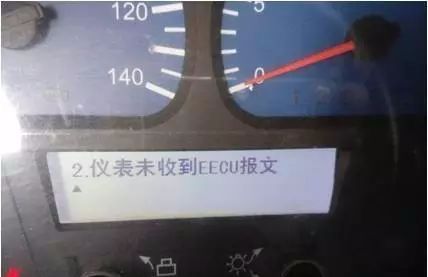
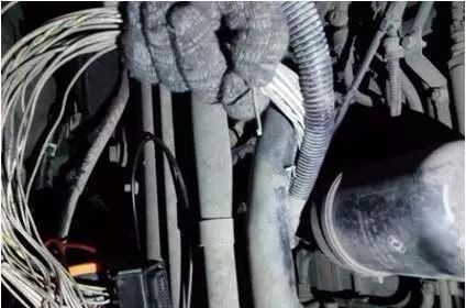
This fault occurs because the engine ECU is not powered and activated, preventing it from sending data information to the instrument, which results in the instrument not receiving data from the ECU,thus reporting: Instrument Did Not Receive EECU Message.
The investigation revealed that the 1.40 pin connected to the computer board by the key was oxidized and disconnected.
This fault generally has three possible causes:
1. The ECU or internal communication module is damaged and cannot send or receive data information.
2. The ECU is not powered and awake, preventing it from sending data information.
3. There is a fault in the CAN line between the ECU and the vehicle computer (VECU).
Case 2
Weichai Bosch 2.2 Post-Processing Reports Fault Code P0050
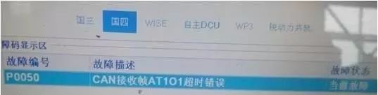
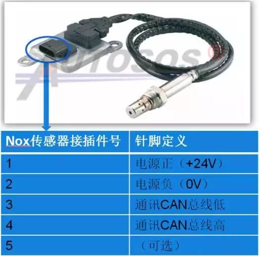
Weichai with Bosch 2.2 post-processing, the current fault code: CAN reception frame AT101 timeout. This fault code indicates that the ECU failed to receive data information sent from the NOx sensor.
Common fault causes are as follows:
1. Abnormal power supply to the NOx sensor, causing the sensor to malfunction and not send data information.
2. Internal fault in the sensor itself, preventing it from sending data information.
3. Faults in the CAN-L and CAN-H lines of the sensor.