Hello, dear students! Good evening!
Today we continue to introduce the technical explanation of S7-200smart Modbus-RTU Communication V20 Inverter.
Students who are interested can leave us a message for interaction~
Let’s get to the main content!

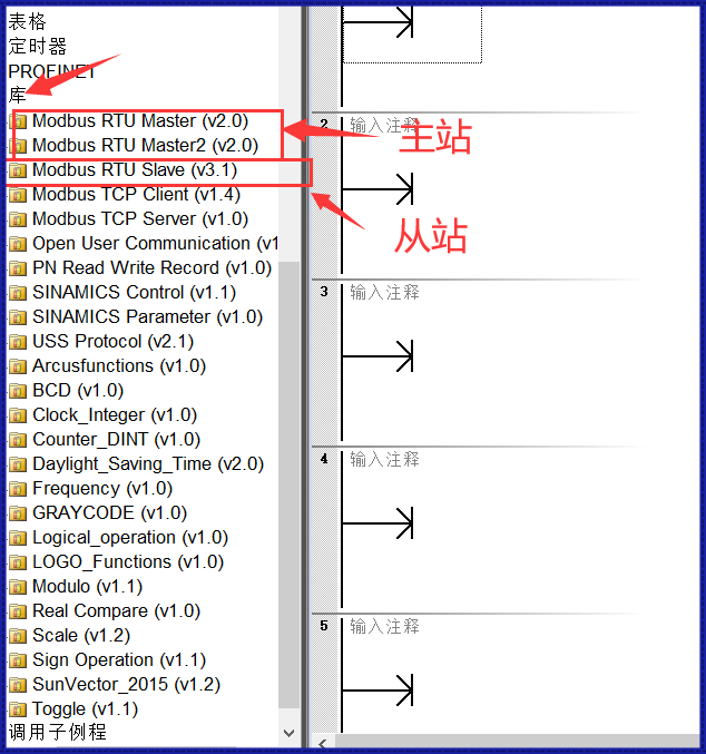
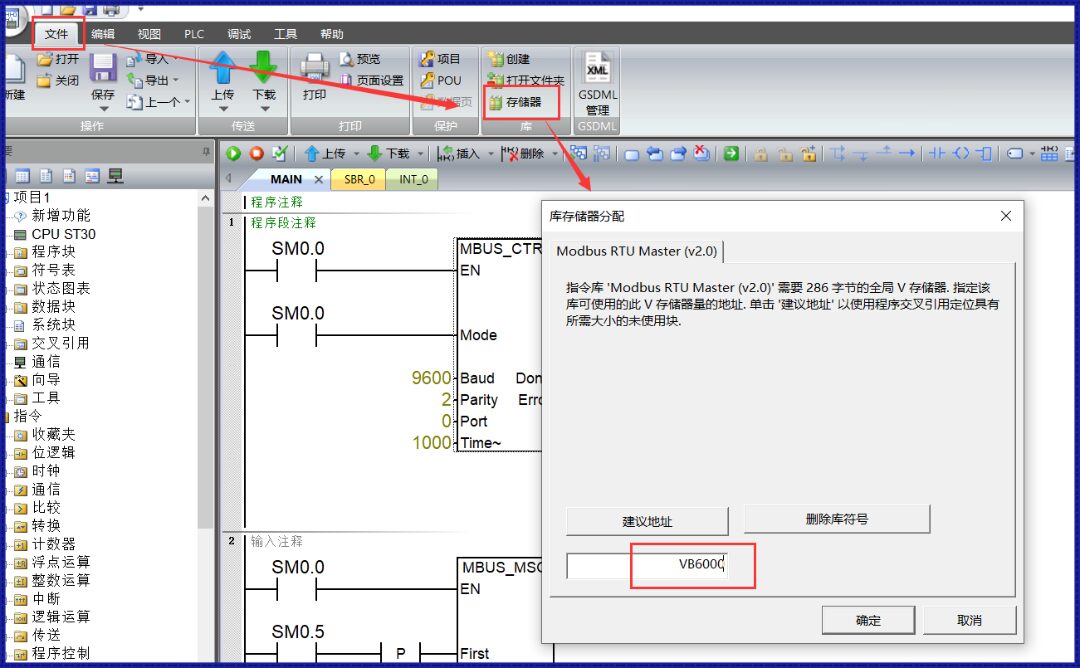
Since we are using the built-in RS-485 port of the S7-200smart CPU; at the same time, in the Modbus-RTU communication between S7-200smart and V20 inverter, S7-200smart acts as the master station, therefore we should choose the Modbus-RTU Master (V2.0) library. If using the signal board expanded RS-485 port, then use the Modbus-RTU Master2 (V2.0) library.
01
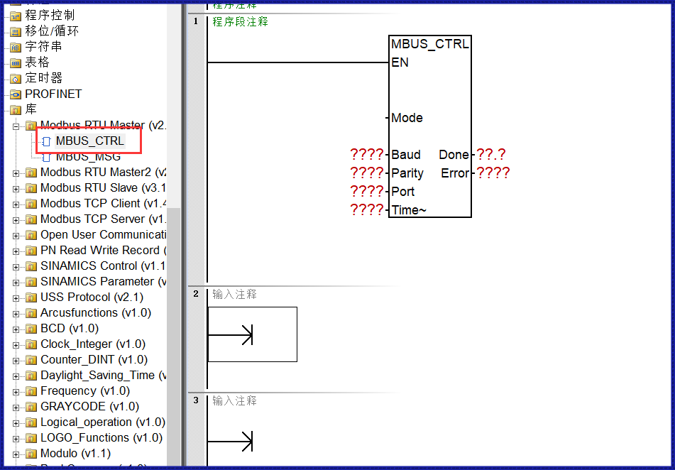
MBUS_CTRL is used by the master station for initialization, aiming to enable the Modbus protocol and configure parameters through the usage of related pin parameters.
02
Meaning of Pins: Detailed meanings of pins can be referred to in the system F1 help.
Mode: 1=Modbus protocol; 0=PPI protocol;
Band: Supported communication baud rates are 1200, 2400, 4800, 9600, 19200, commonly used is 9600.
Parity: Check methods include 0 no check; 1 odd check; 2 even check;
Port0: 0=CPU integrated RS 485 communication port; 1=optional CM01 signal board;
Timeout: The time the master station waits for the slave station’s response, in milliseconds, typical setting value is 1000 milliseconds (1 second), the allowable range is 1-32767; (commonly used is 1000).
Done: Initialization complete, this bit will automatically be set to 1;
Error: Communication error, specific error meanings refer to the Error parameter.
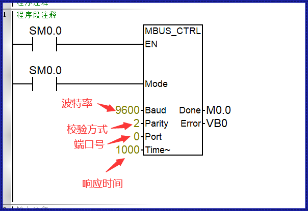
03
Actual filling situation takes S7-200smart reading the V20 inverter frequency as an example, see the image below
01
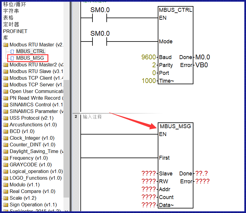
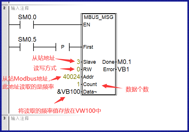
MBUS_MSG is used by the master station to send communication requests and process responses.
02
Meaning of Pins: Detailed meanings of pins can be referred to in the system F1 help.
En Enable: Only one read/write function (i.e. MBUS_MSG) can be activated at a time;
First Read/Write Request: Each time there is a new read/write request, this pin must be used and triggered with a pulse;
Slave Address: Selectable range 0-247, where 0 is the broadcast address, the actual range is 1-247;
RW Read/Write Request: 0 = read, 1 = write;
Addr Starting Modbus Address of the Slave: Choose the starting Modbus address of the slave to read/write based on actual requirements (e.g., 40001);
Count Number of Data: Allocated number of data to read or write during communication (number of bits or words);
DataPtr Data Pointer: Points to the starting address; if the master reads, the data read back will be placed in this data area; if the master writes, the data to be written will be placed in this data area;
Done Completion Bit: Read/write function completed, this bit will automatically be set to 1;
Error Error Code: Communication error, specific error meanings refer to the Error parameter;
03
Actual filling situation takes S7-200smart reading the V20 inverter frequency as an example, see the image below.

Alright, that’s all for today’s technical explanation. Practice more, learn more, and improve more.
Utilizing your fragmented time, doing something beneficial for yourself will bring a great sense of accomplishment~
Students who need to know about other courses can click Read the original text to enter our official website~
Click here to read the original text